高波前拟合精度的紧凑型音圈变形镜
1 Introduction
In adaptive optical imaging systems, the Deformable Mirror (DM) is usually used to correct aberrations induced by atmospheric turbulence[1]. Different kinds of DMs have been investigated, such as the piezoelectric (PZT) DM[2], magnetic fluid DM[3], electrostatic DM[4], and voice coil DM (VCDM)[5]. Compared with others, the VCDM has many merits, such as linear responses, a large phase stroke, and low voltage, which is suitable for the next generation of DMs with research spanning back to the 1990 s[6].
In 1993, P. Salinari demonstrated a VCDM as a deformable secondary mirror of the Large Binoculars Telescope (LBT). After that, a prototype of P36 was manufactured and demonstrated based on the principle. The MMT336 DM was fabricated in 2000 and installed on the Multi-mirror Telescope (MMT) in 2002[7]. MMT was the first ground-based optical telescope equipped with a VCDM as the adaptive secondary mirror, followed by the Large Binoculars Telescope, the Magellan Telescope, the Very Large Telescope, and others[8]. However, the diameter of a Voice Coil Actuator (VCA) in these DMs ranges between 20 mm and 30 mm, which leads to a large VCDM with an aperture of about 1000 mm. Large VCAs also require cooling systems. In addition, its coupling coefficient is generally larger than 60%, which is much larger than that of PZT-based DM. For a compact VCDM, a relatively small coupling coefficient is valuable to obtain high wavefront correction precision. Finally, it should be noted that it is expensive to use custom VCDMs with complex structures. In applications, such as retinal imaging, biological microscopy, and optical communications, a compact and relatively inexpensive DM with high electro-optical performance is necessary.
Several kinds of compact DMs have been investigated, such as the membrane DM[9], micro-electro-mechanical system (MEMS) DM[10], and magnetic DM[11]. The membrane DM is composed of a flexible silicon membrane supported by an underlying array of electrostatic parallel plate actuators. Usually, its phase stoke is not large, and its driving voltage is relatively high at about several tens of volts[12]. In addition, a dedicated electronic device is needed to linearize its actuation. Although the MEMS DM has a large number of actuators, its phase stroke is only about several micrometers[13], limiting its applications as a wavefront corrector in adaptive optics systems. The magnetic DM uses small planar coils on silicon. Therefore, to generate large enough force to push or pull in the thin mirror of a magnetic DM, a relatively large current is necessary, which leads to high power dissipation. VCDMs have the merits of low cost and linear response compared to PZT DM. However, standard VCDMs have two obvious drawbacks: (1) large coil diameters with a high cost and relatively low bandwidth, (2) high coupling coefficient and a large current that cannot be used in a compact VCDM. Multiple compact VCDMs from ALPAO have a pitch of 0.8 mm, 1.5 mm, 2.5 mm, and 5 mm, and the number of actuators ranges from 69 to 3228. They have a non-linearity below 3%, and a hysteresis as low as 2%. However, these VCDMs use the MEMS manufacturing process resulting in high costs. In this paper, an alternative compact VCDM is presented by deriving theoretical equations that could guide a reasonable design. The designed micro VCA has a small diameter of about 2 mm, which is only about a tenth of a standard one and allows a compact VCDM with a high density of actuators. Different factors such as phase stroke, resonant frequency, and power dissipation were analyzed. The VCDM's structure has been simplified and optimized to realize a low coupling coefficient and good electro-optical performances. In fact, these parameters are influenced by the interactions among multi-physical fields, such as electromagnetic, thermal, stress and strain fields. For example, increasing the current in a voice coil can produce a large electromagnetic force and increase its phase stroke. However, it can also lead to a large thermal dissipation, and even distort the VCDM’s thin mirror. Therefore, theoretical mathematical equations were derived to find reasonable requirements from applications. Further, numerical simulations based on the finite element method were used to optimize the compact VCDM.
In the paper, the compact VCDM with high electro-optical performance is theoretically designed and demonstrated. In section 2, a theoretical analysis is given according to their typical applications. In section 3, its structure is designed, and its micro VCA is optimized based on electromagnetic finite element theory. In section 4, the temporal and spatial properties of the compact VCDM using optimized micro VCA are discussed. Finally, conclusions are given in section 5.
2 Theory of the compact VCDM
There are many factors that affect the electro-optical performance of a compact VCDM, such as phase stroke, the electromagnetic force of the micro VCA, the power dissipation and efficiency of the micro VCA, the response time of the VCDM and the coupling coefficient. A DM with only one or two of them with excellent values as reported in the references could not really lead to a high electro-optical performance for a compact VCDM[5]. Therefore, it is necessary to systematically analyze the requirements from the applications according to electromagnetic theory.
2.1 Requirement of phase stroke and frequency for the VCDM
The phase stroke of the VCDM is determined by the stroke of its micro VCA. The phase stroke requirement of a DM could be different according to the media that the light beam propagates through, such as atmospheric turbulence or the human eye. For airborne/spaceborne adaptive optics applications, according to Noll’s theory, if the first J Zernike modes of the distortion have been corrected, the mean square residual error can be calculated as follows:
where〈ϕ2〉is the phase variance and aj is the Zernike polynomial coefficient[14]. When J is 1, Eq. (1) can be approximated as
where D is the telescope aperture and r0 is the atmospheric turbulence coherent length generally ranging from 5 cm to 20 cm for λ=550 nm[15]. For an r0 of 5 cm and D of 8.4 m, Δ1 is equal to 5268 rad2 according to Eq. (2). The wavefront that the DM has to correct is about 5 times larger than the residual[16]. In addition, considering the reflection doubling effect, the required mechanical stroke of a VCA for atmospheric turbulence correction could be calculated as
Unlike the aberrations of atmospheric turbulence, those in the human eye are difficult to represent using a theoretical model. Therefore, we take the approximate requirements for the phase stroke from experimental statistical results reported by other groups. Doble N[17] measured human eye aberrations on two different populations at the University of Rochester and Indiana University using a Shack-Hartmann wavefront sensor. The maximum PV of the wavefront is up to 53 μm for a pupil diameter ranging from 2 mm to 7.5 mm. Zhao J L[18] performed an aberration analysis on 332 healthy eyes and 344 diseased eyes. For a wavelength of 550 nm and a pupil diameter of 6 mm, the PV value of the total-order aberrations was (24.1±10.9) μm in the normal group and (19.0±10.05) μm in the abnormal group[18]. Therefore, the mechanical phase stroke of a micro VCA should be at least 26.5 μm for human eye aberration correction.
According to the discussions above, retinal imaging requires a larger phase stroke compared to astronomical observation. Considering the static aberration in the optical path, the compact VCDM needs a margin of phase modulation. The phase stroke of the compact VCDM should be at least 27 μm.
The bandwidth of the VCDM should be high enough to meet the frequency of atmospheric turbulence aberrations[19]. The Greenwood frequency is usually used to characterize atmospheric turbulence and it could be approximated as:
where v is the wind speed, and r0 is the atmospheric turbulence coherence length. And the Greenwood frequency in an observatory station is necessarily larger than 50 Hz.
2.2 Key parameters of micro VCA
The electromagnetic force generated by the micro VCA directly determines the phase stroke of the VCDM[20]. A micro VCA as shown in Fig.1. includes mainly two parts: one is the permanent magnet on the top and the other is the voice coil. When a current is passed through the voice coil, the magnet connected to the thin mirror of the DM is movable, which pushes or pulls the local thin mirror and generates deformation.
In Fig.1, rm is the magnet’s radius, hm is its height, dc-in is the coil’s inner diameter, dc-out is the coil’s outer diameter, hc is the coil’s height, and hg is the height of the air gap. When the permanent magnet in the VCA is in the magnetic field generated by the current-carrying coil, the electromagnetic force could be calculated as
where V is the volume of a permanent magnet, and Br is the remanence of the permanent magnet,
To quantify analyze the performance of the micro VCA, efficiency ε is used as the evaluation factor[21]. It could be calculated as
where the unit of ε is N/√W, F is the electromagnetic force, I is the current through the coil, and R is the resistance of the coil. The larger the efficiency of the VCA, the better it is.
3 Design and optimization of the compact VCDM
The sectional view of the compact VCDM is shown in Fig.2(a). The structure of compact VCDM mainly includes ten components. The pupil diameter in the front shell is 17 mm. Fig.2(b) shows the arrangement of VCAs. Sixty-nine VCAs are arranged in a square array under the thin mirror. A single micro VCA contains a permanent magnet and a voice coil. One end of the strut is attached to a micro VCA, while the other is attached to the back of the thin mirror. The strut transmits the force of an actuator to the thin mirror and deforms the local surface of the thin mirror. The shaft of a strut is mounted with a spring in the spring-fixing plate. This structure provides the micro VCA with axial stiffness, which overcomes the problem where an actuator’s mover is directly suspended on the mirror in traditional VCDMs[22]. The thin mirror is formed by spinning and depositing polyimide liquid on a highly smooth substrate. The assembly process of the DM can be found in reference [16].
To realize the compact VCDM, the pitch of actuators must be small enough. The geometrical shape of the VCA array as shown in Fig.2 is square with a pitch of 2.5 mm. To ensure that there is an installation gap between the actuators, the diameter of a VCA should not be greater than 2.2 mm. At the same time, the mover of the VCA should be as small as possible to get a faster response, so the initial height of the magnet is set to 0.1 mm. The geometrical model of the VCAs is built and simulated with FEM. The initial geometrical sizes for the micro VCA are defined as follows: (1) a permanent magnet with a radius of 1 mm and a height of 0.1 mm; (2) a coil with an inner diameter of 0.2 mm, an outer diameter of 2.2 mm, and a height of 1 mm. To meet the phase stroke requirements calculated in Section 2.1 and reserve redundancy, the initial size of the air gap is set to 50 μm. The permanent magnet is made of NdFe35. The parameters that need to be optimized are listed in Tab. 1.
表 1. Parameters for micro VCAs to be optimized
Table 1. Parameters for micro VCAs to be optimized
|
In our previous work[21], for axial and radial magnetization directions of the permanent magnet shown in Fig.3(a) and 3(c), the outputted force generated by radial magnetization must be larger than that of the axial magnetization. However, it is difficult to realize radial magnetization for the permanent magnet with so small a size. In addition, parallel magnetization as shown in Fig.3(b) is easy to achieve.
图 3.
Fig. 3. Magnetization directions of the permanent magnet. (a) Axial magnetization, (b) parallel magnetization, (c) radial magnetization
Fig.4 (color online) shows the comparison of electromagnetic force in three magnetization directions. From Fig.4 It can be seen that the effect of parallel magnetization is very good, and the electromagnetic force under the same current is close to that of radial magnetization.
图 4.
Fig. 4. Electromagnetic force as a function of current for the permanent magnet at different magnetization directions
Fig.5 (color online) shows the optimization results of the structural parameters under parallel magnetization and radial magnetization where parallel magnetization is represented as (P) radial magnetization as (R).
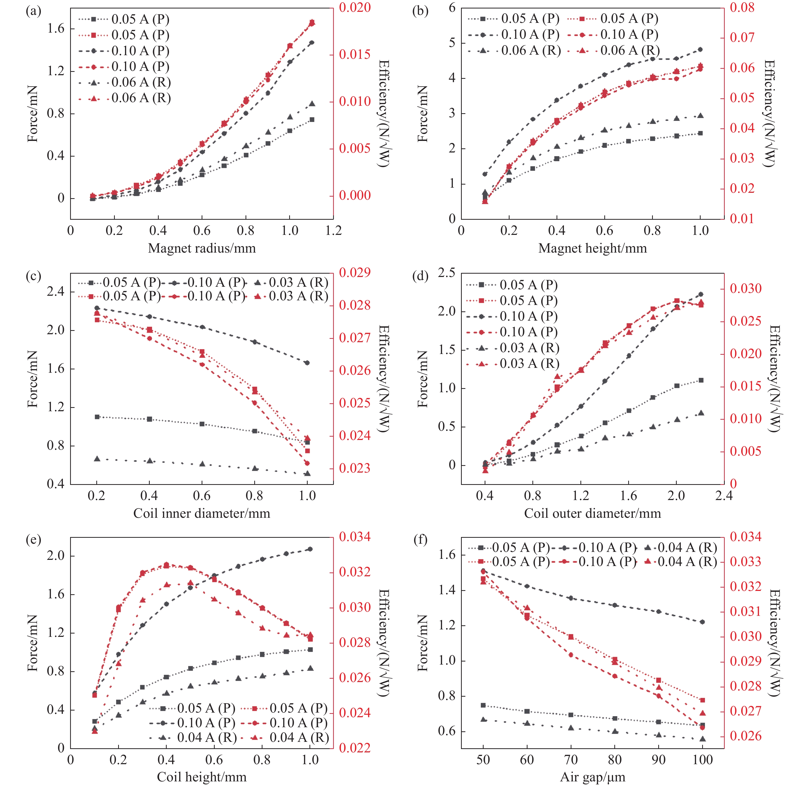
图 5.
Fig. 5. Force and efficiency as a function of the VCA’s structural parameters: (a) permanent magnet radius; (b) permanent magnet height; (c) coil inner diameter; (d) coil outer diameter; (e) coil height; (f) air gap
Fig.5(a) and Fig.5(b) show the electromagnetic force and efficiency ε as a function of magnet radius and height, respectively. The trade-off between efficiency and size is what determines the parameters. The larger the magnet radius and magnet height, the larger the electromagnetic force and efficiency. Their differences are the slopes of the electromagnetic force and efficiency curves. It should be noted that the permanent magnet is the determinant of the VCA, and increasing the permanent magnet’s volume will reduce the response speed of the VCA. Therefore, the optimized radius of the magnet is selected as 1 mm and its optimized height is selected as 0.2 mm. The results in Fig.5(c) indicate that as the inner diameter of the coil increases, both the electromagnetic force and the efficiency decrease. The optimized inner diameter of the coil is 0.2 mm and according to Fig.5(d), the optimized outer diameter of the coil is 2 mm. The change of force and efficiency in Fig.5(e) are slightly different from the others. Although the electromagnetic force increases with the height of the coil, its efficiency first increases and then decreases. This is because the wire being far away from the permanent magnet means that it contributes less to the electromagnetic force. Considering the efficiency of the actuator, the optimized coil height is 0.4 mm. Fig.5(f) shows that the larger the air gap, the smaller the electromagnetic force and efficiency. Therefore, the optimized air gap of the micro VCA is 50 μm.
The optimized VCA has a diameter of 2 mm and a height of 0.65 mm. It is only one-tenth the size of the actuators for traditional VCDMs. Fig.6 (color online) shows electromagnetic force and efficiency as a function of current before and after optimization. The obtained results indicate that the electromagnetic force and efficiency increased substantially after optimization. The output electromagnetic force of the VCA with optimized structural parameters increased by a factor of 10%. The results confirm that the efficiency also notably increased. The efficiency of the VCA before optimization is 0.016 N/√W and it is up to 0.032 N/√W after optimization.
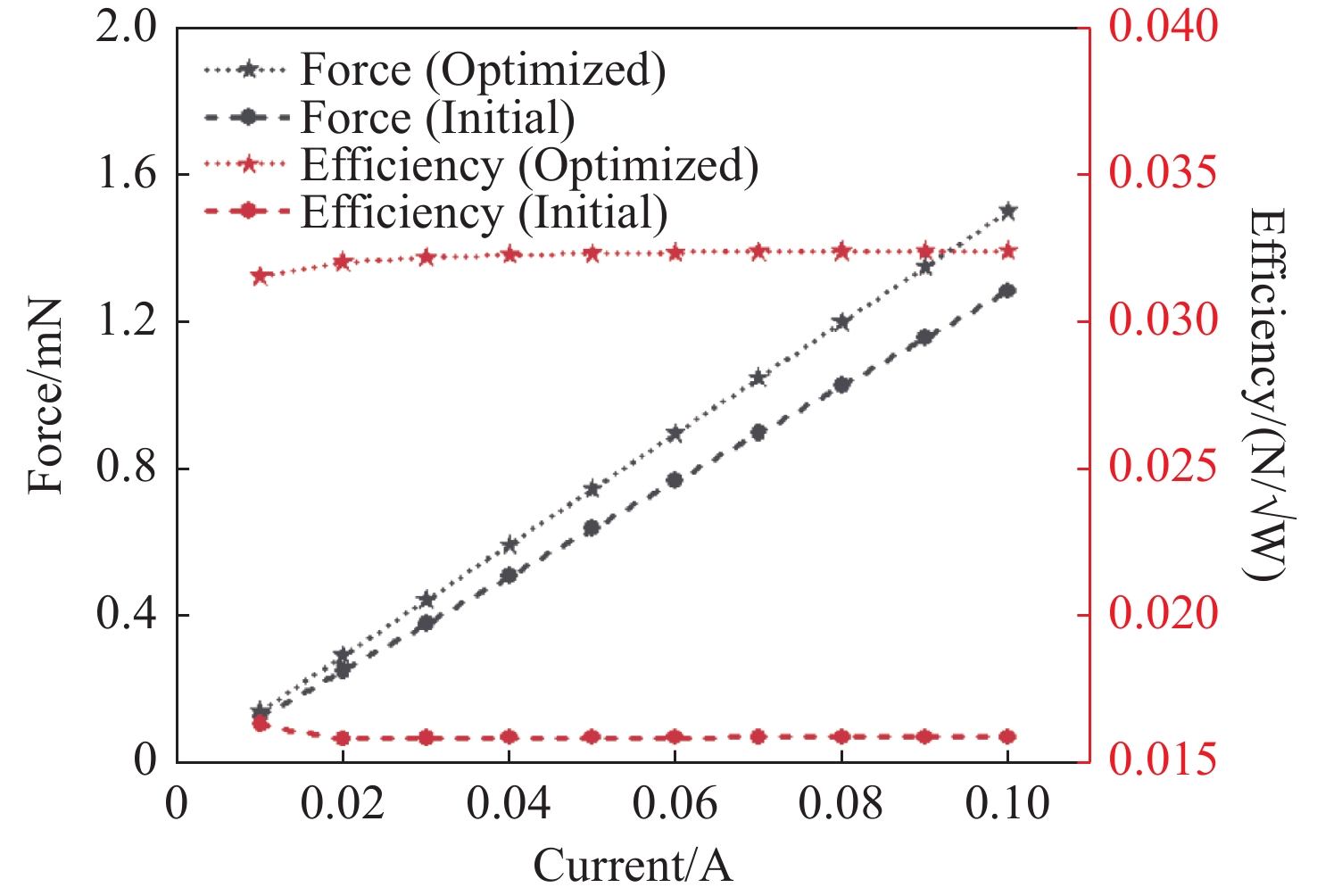
图 6.
Fig. 6. Electromagnetic force and efficiency as a function of current (Circle line, before optimization; pentagram line, after optimization)
4 Discussions
4.1 Aberration of the thin mirror due to the thermal effect
To investigate the effect of temperature increases from the current in VCAs on the thin mirror, the model of a VCA is analyzed using Maxwell and steady-state thermal modules in Ansys software. The procedure of thermal analysis is shown in Fig.7 (color online).
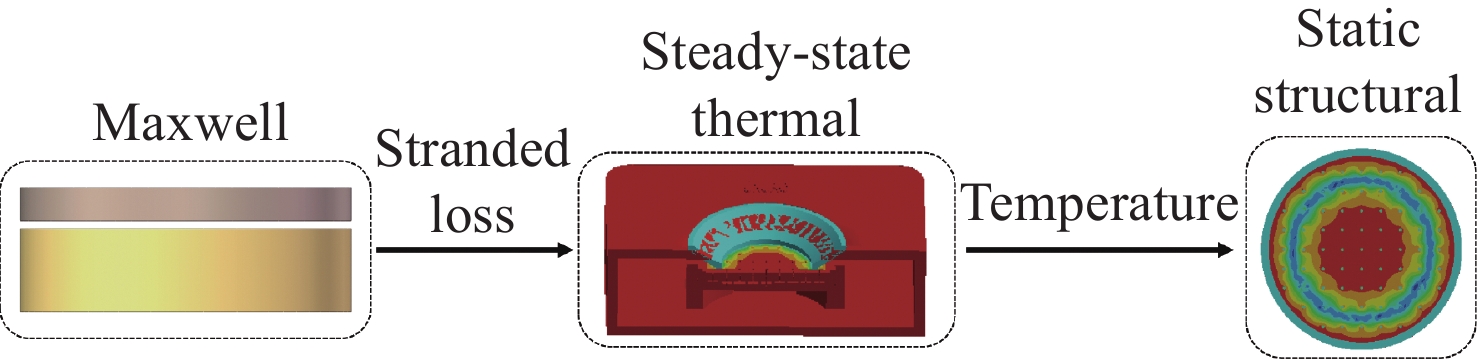
In compact DMs, active cooling elements such as air cooling and water cooling are generally not used. The thermal convection of all parts in the VCDM is through the air. In the ANSYS steady-state thermal module, the air convection heat transfer coefficient is set to 5 W/(m2K)[23]. According to the mechanical model of the VCDM, as shown in Fig.2, the internal heat generation of the voice coil is introduced by the ohmic loss calculated by the Maxwell module. After that, the thin mirror temperature obtained by the steady-state thermal module is transferred to the static structural module to calculate the thermal deformation of the thin mirror.
The mirror material is CP1 Polyimide from NeXolve[24]. O-rings, springs, and struts are made of 316 Stainless Steel. The adhesive between the struts and the mirror is Epoxy. The material of the permanent magnet is NdFe35, and the material of the coil is copper. To accelerate heat dissipation, the shell of the DM, spring fixing plate, and baseplate are all made of aluminum alloy. The parameters of the adopted materials are listed in Tab. 2.
表 2. Material parameters uesd in thermal analysis
Table 2. Material parameters uesd in thermal analysis
|
Fig.8(a) (color online) shows the temperature of the VCDM’s thin mirror as a function of currents. The maximum temperature of the mirror surface increases along with the current. When the current is 0.1 A corresponding to a current density of 10 A/mm2, the temperature rise of the VCDM is about 1 degree Celsius. Fig.8(b) (color online) shows the thermal deformation of the thin mirror due to non-uniform distribution of rising temperatures. It indicates that the PV of the thin mirror deformation increases along with the current. When the current density is 6 A/mm2 corresponding to 0.06 A, the PV is 12.36 nm, which is about 0.022λ for λ=550 nm. Therefore, the maximum control current of a single VCA should not be larger than 0.06 A for good thermal stability. At this time, the temperature and the deformation of the thin mirror are shown in the inserted figures of Fig.8(a) and Fig.8(b).
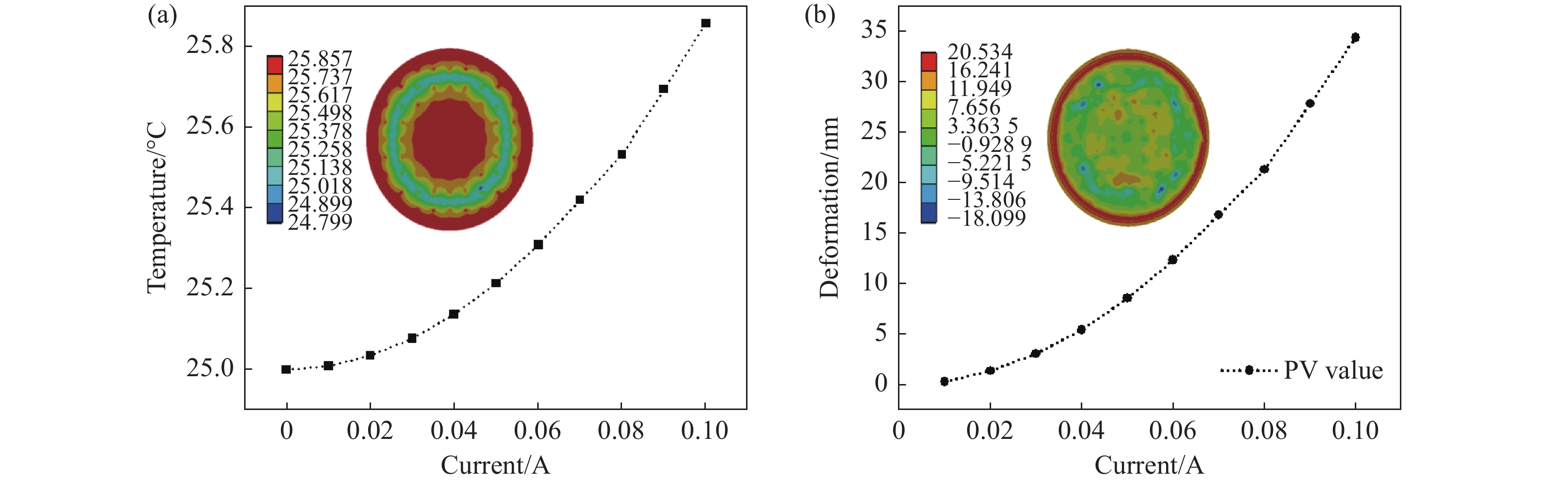
图 8.
Fig. 8. Temperature and thermal deformation of the VCDM’s thin mirror as a function of current. (a) The temperature of the thin mirror as a function of current. The inset shows the temperature chart of the thin mirror when the current is 0.1 A. (b) The thermal deformation chart of the mirror surface as a function of current. The inset shows the deformation chart of the thin mirror when the current is 0.06 A
4.2 First resonance frequency
The first resonance frequency of the VCDM is mainly related to the mirror and the actuator’s stiffness. When the mirror material is selected, the mirror’s stiffness is determined by its thickness, and the stiffness of the VCA is dominated by the spring. As shown in Fig.9, the first resonance frequency is positively correlated with the spring’s stiffness for a given mirror thickness. However, for unchanging spring stiffnesses, the first resonance frequency increases and then decreases with an increasing mirror thickness, which shows that there is an extreme point in the relationship. The frame rate of the Adaptive Optics (AO) system should be 10 to 30 times higher than the bandwidth of the closed-loop system. Therefore, a mirror thickness ranging from 20 µm to 50 µm is preferable.
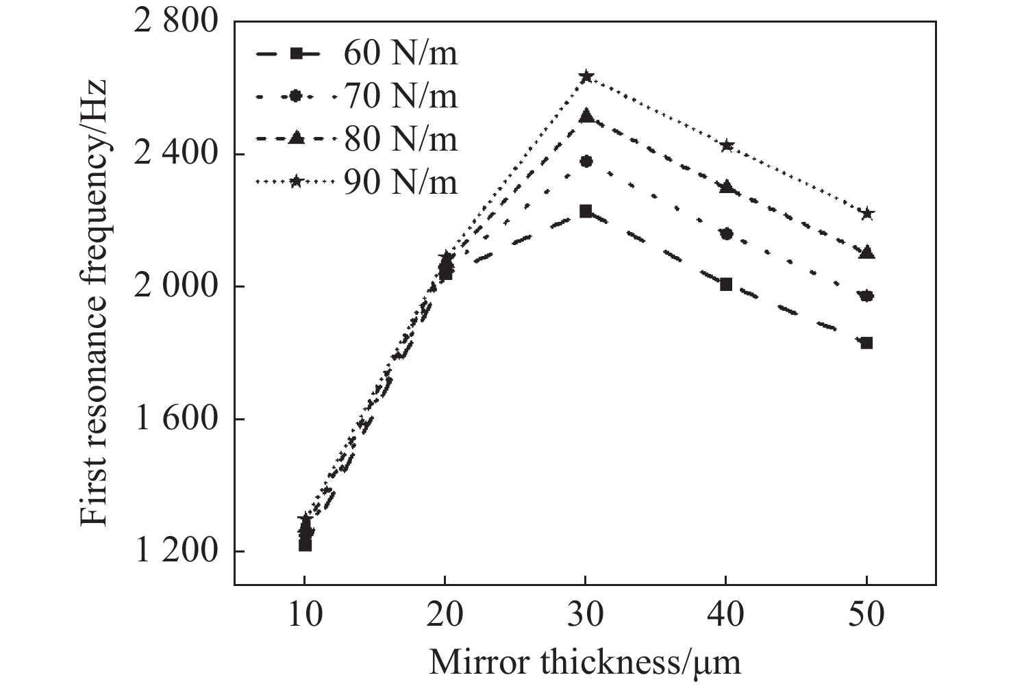
图 9.
Fig. 9. Relationship between first resonance frequency of the DM and mirror thickness under different spring's stiffnesses
4.3 Wavefront fitting precision
The wavefront fitting precision of the VCDM is important for AO wavefront correction. The influence function of the VCDM could also be expressed as[25]:
where Z(r) is the thin mirror deformation at a distance of r, k is the deformation of the mirror at the position of the central actuator, ω is the coupling coefficient that indicating the influence of the central actuator on neighboring actuators, the actuator spacing d0 is 2.5 mm, and α is the Gaussian index.
The coupling coefficient ω, a key indicator of the DM, is mainly influenced by the thickness of the mirror and the stiffness of the actuator. There is an optimal range of coupling coefficients for a given DM; too large or too small will affect the performance of the system[26]. As shown in Fig.10, the coupling coefficient increases with mirror thickness. In addition, the larger the stiffness, the smaller the coupling coefficient.
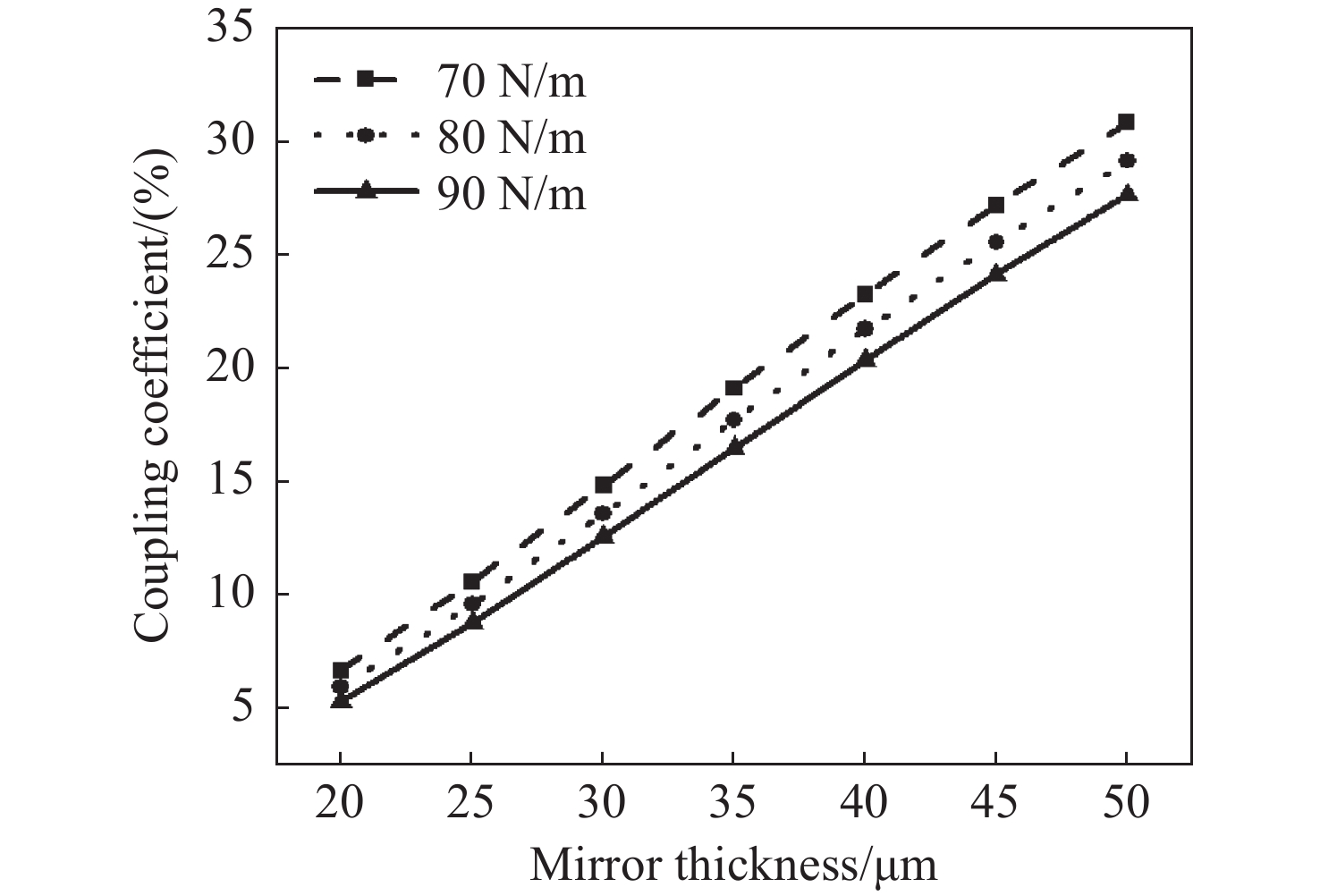
图 10.
Fig. 10. Relationship between coupling coefficient of the DM and mirror thickness under different spring's stiffnesses
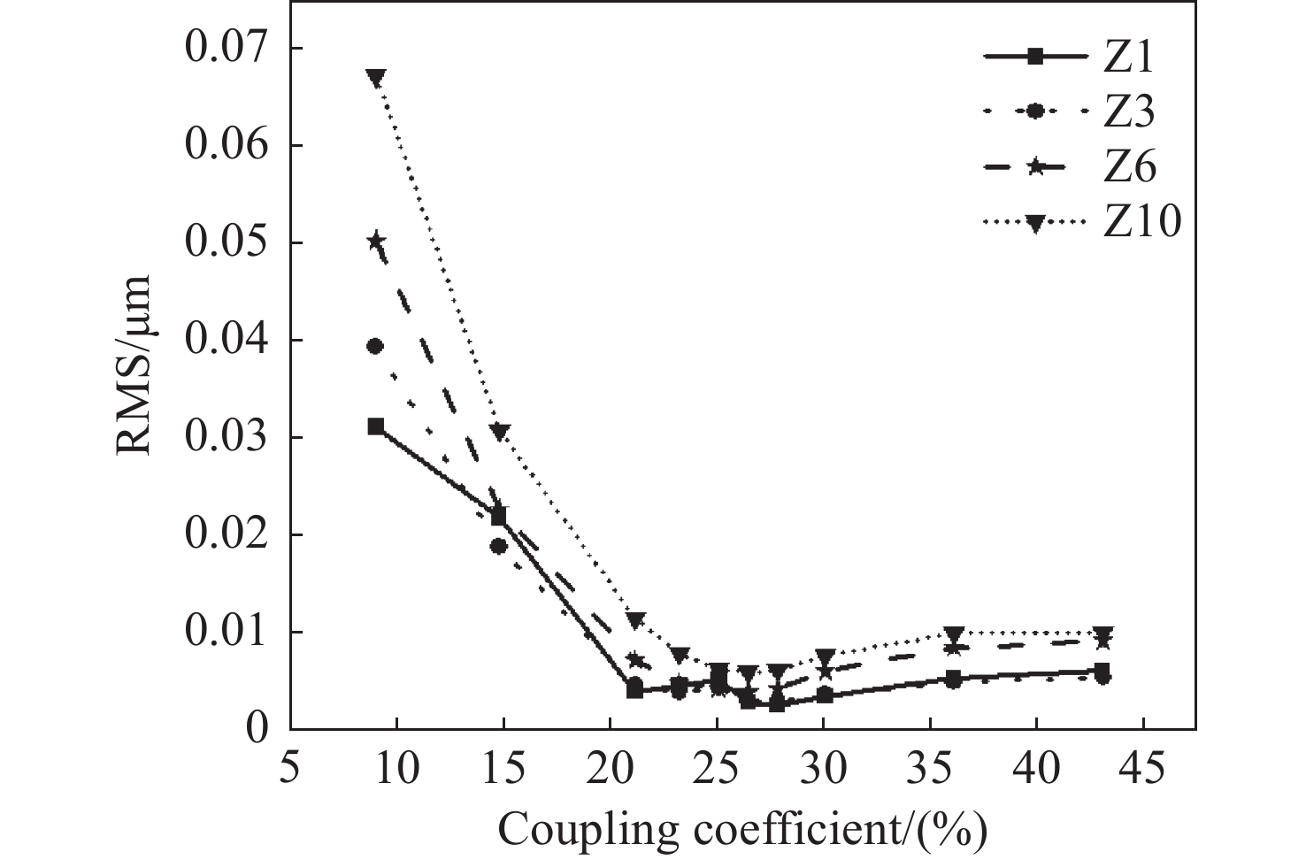
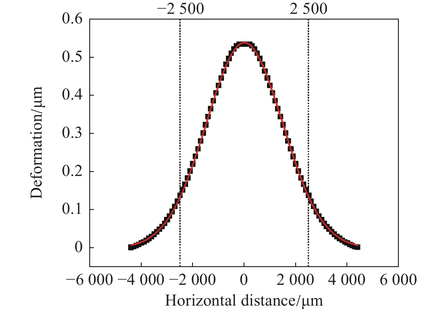
The wavefront fitting errors as a function of the coupling coefficient are shown in Fig.11 for four Zernike modes Z1, Z3, Z6, and Z10 with a PV value of 8 μm. The results indicate that with an increase in the coupling coefficient, errors decrease rapidly at first and then increase slowly. The optimal coupling coefficient for the compact VCDM is about 25%, which is much smaller than that of a standard VCDM with a value larger than 60%. Generally, a relatively low coupling coefficient is preferable for high wavefront correction precision. A VCDM model named S1 with a mirror thickness of 50 μm and an actuator stiffness of 90 N/m was built. Its influence function is shown in Fig.12. Sixty-nine VCAs are arranged in a square array under the thin mirror. The pitch of S1 is 2.5 mm, the coupling coefficient is 24.9% and the first resonance frequency is 2220 Hz.
The MATLAB codes were programmed to complete the wavefront fitting and residual calculation according to the influence functions. It should be pointed out that, to simplify the calculation model, the error caused by thermal deformation and response delay is not considered. In the fitting experiment, S1 is actuated to generate Zernike shapes with a PV value of 1 μm. Fig.13 shows the wavefront Root Mean Square (RMS) of the first 35 Zernike modes and the residual wavefront RMS after fitting. The results indicate that the fitting effect of S1 for the first 35 Zernike modes is very good and the RMS is always less than 30 nm. Compared with the large 121-element VCDM designed by Zhang Z G, the wavefront fitting precision of S1 is higher by 15%[27]. Fig.14 (color online) shows the wavefront fitting results of S1 for a complex random aberration. The complex random aberration consists of 90 Zernike modes and its PV value is 1.647 μm. It can be seen that the fitting wavefront generated by S1 is very similar to the original wavefront. The VCDM S1 reduces the RMS of the complex random aberration from 0.2722 μm to 0.0239 μm. The above results show that S1 has high wavefront fitting precision.
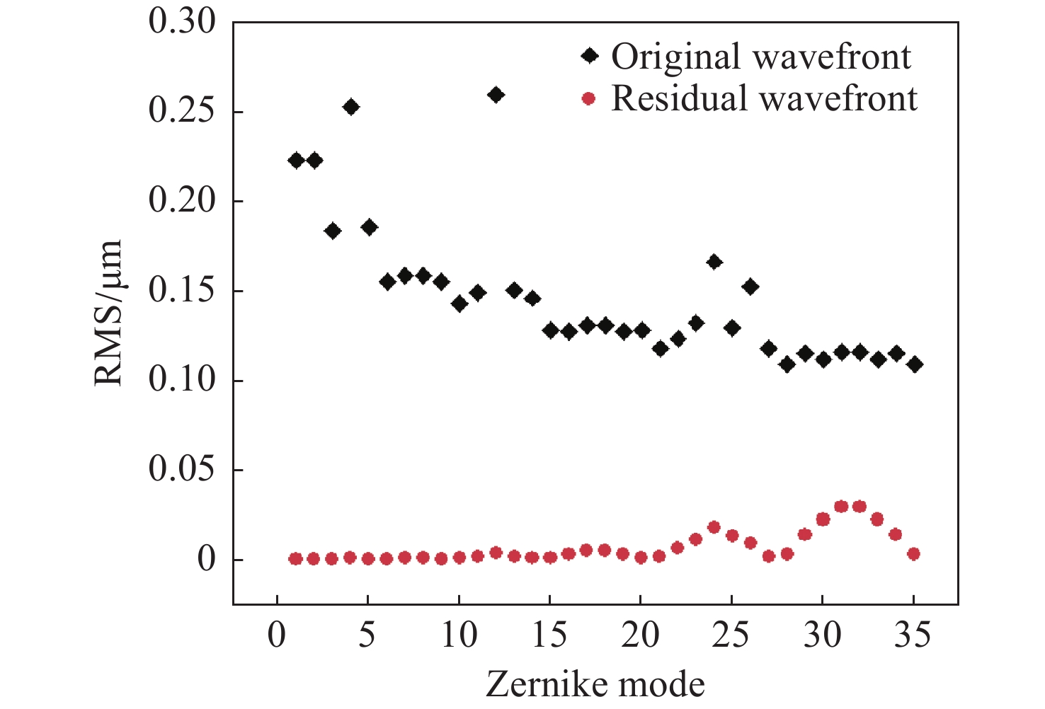
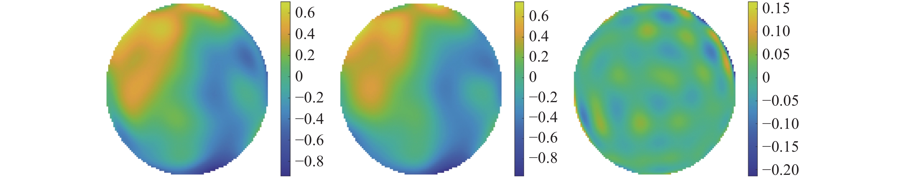
图 14.
Fig. 14. The wavefront fitting results of S1 for complex random aberrations. From left to right, there is the original wavefront, the fitting wavefront and the residual wavefront
5 Conclusion
The VCDM has many merits, such as being hysteresis-free, requiring low voltage, having a large phase stroke and so on. However, there are many limitations and factors in VCDMs that will affect their performance. In the paper, to design a compact VCDM with improved properties, an analytical expression based on electromagnetic theory is systematically built, which includes its parameters such as phase stroke, force, efficiency, and frequency. They guide the design and reasonable optimization of the compact VCDM. The thin mirror of the VCDM is made of polyimide and is coated with a thin layer of evaporated aluminum in order to make it optically reflective. The struts of micro VCAs are installed in the spring fixing plate, whose springs provide micro VCAs with axial stiffness. This structure makes it possible for the VCDM to have a higher operating bandwidth. Based on multiparameter analysis and finite element analysis using ANSYS, a well-optimized VCDM is obtained with a micro VCA of 2 mm in diameter and an efficiency of 0.032 N/√W. The maximum current of a micro VCA is 0.06 A, which gives the VCDM excellent thermal stability. The temperature difference of the thin mirror is less than 0.4 °C at the maximum current of 0.06 A, and the thermal deformation of the thin mirror is only 12.36 nm. The first resonance frequency of the 69-element compact VCDM S1 is 2220 Hz. High wavefront fitting precision with a relatively low coupling coefficient of about 25% is also demonstrated in this paper. The fitting results of Zernike aberrations show that the wavefront fitting precision of the compact VCDM increased by 15% compared with traditional VCDM. In addition, S1 can reduce the wavefront RMS of complex random aberrations to less than 10%. The above results indicate that the compact VCDM can satisfy the requirements of miniaturized adaptive optics systems. The design and optimization methods are also valuable for the design of other kinds of DMs. Our design decreases the development cost of VCDMs and obtains a compact version with high electro-optical performance.
[1] HU L F, LIU CH, SHEN W, , et al. Advancement of adaptive optics in astronomical observation[J]. Scientia Sinica Physica, Mechanica & Astronomica, 2017, 47(8): 084202.
[3] WU ZH ZH, ZHANG T Y, MBEMBA D, , et al. Wavefront sensorless aberration correction with magnetic fluid deformable mirror for laser focus control in optical tweezer system[J]. IEEE Transactions on Magnetics, 2021, 57(1): 1-6.
[15] HARDY J W, THOMPSON L. Adaptive optics for astronomical telescopes[J]. Physics Today, 2000, 53(4): 69.
[16] HAMELINCK R F M M. Adaptive defmable mirr: based on electromagic actuats[D]. Eindhoven: Technische Universiteit Eindhoven, 2010: 2325.
[27] 张志高. 模块化音圈变形镜的结构设计与性能研究[D]. 无锡: 江南大学, 2022.
ZHANG ZH G. Structure design perfmance research of modular voice coil defmable mirr[D]. Wuxi: Jiangnan University, 2022. (in Chinese).
Article Outline
胡立发, 姜律, 胡启立, 徐星宇, 黄杨, 吴晶晶, 俞琳. 高波前拟合精度的紧凑型音圈变形镜[J]. 中国光学, 2023, 16(6): 1463. Li-fa HU, Lv JIANG, Qi-li HU, Xing-yu XU, Yang HUANG, Jing-jing WU, Lin YU. Compact voice coil deformable mirror with high wavefront fitting precision[J]. Chinese Optics, 2023, 16(6): 1463.


 PDF全文
PDF全文
