Opto-Electronic Science, 2023, 2 (2): 220024, Published Online: Apr. 27, 2023  

Measurement of optical coherence structures of random optical fields using generalized Arago spot experiment

Xin Liu 1,2Qian Chen 1,2Jun Zeng 1,2,*Yangjian Cai 1,2,**Chunhao Liang 1,2,***
Author Affiliations
1 Shandong Provincial Engineering and Technical Center of Light Manipulation & Shandong Provincial Key Laboratory of Optics and Photonic Devices, School of Physics and Electronics, Shandong Normal University, Jinan 250014, China
2 Collaborative Innovation Center of Light Manipulations and Applications, Shandong Normal University, Jinan 250358, China
Abstract
The optical coherence structures of random optical fields can determine beam propagation behavior, light–matter interactions, etc. Their performance makes a light beam robust against turbulence, scattering, and distortion. Recently, we proposed optical coherence encryption and robust far-field optical imaging techniques. All related applications place a high demand on precision in the experimental measurements of complex optical coherence structures, including their real and imaginary parts. Past studies on these measurements have mainly adopted theoretical mathematical approximations, limited to Gaussian statistic involving speckle statistic (time-consuming), or used complicated and delicate optical systems in the laboratory. In this study, we provide: a robust, convenient, and fast protocol to measure the optical coherence structures of random optical fields via generalized Arago (or Poisson) spot experiments with rigorous mathematical solutions. Our proposal only requires to capture the intensity thrice, and is applicable to any optical coherence structures, regardless of their type or optical statistics. The theoretical and experimental results demonstrated that the real and imaginary parts of the structures could be simultaneously recovered with high precision. We believe that such a protocol can be widely employed in phase measurement, optical imaging, and image transfer.

1 Introduction

The optical coherence structure, as one intrinsic property of a light beam, plays a pivotal role in not only optical interference but also a wide range of applications. The optical coherence theory provides a viable platform for studying partially coherent beams (PCBs)1, 2. Such beams are characterized by a cross-spectral density (CSD) function in the spatial-frequency domain or a mutual coherence function (MCF) in the spatial-time domain. PCBs, with the prescribed optical coherence structures, have various applications in optical coherence tomography3-5, optical communication6, phase imaging7-9, incoherent source reconstruction10, and super-resolution optical imaging11, 12; notably, they can be imaged through scatter media13. We recently proposed optical coherence imaging, wherein optical coherence structure, as the information carrier, could realize robust far-field optical imaging14-17. It can be immune to atmospheric turbulence and opaque obstacles. On the other hand, there are multifarious theoretical and experimental methods proposed to generate predetermined PCBs, with two techniques being the most popular. The first operates based on the van Cittert–Zernike theorem18, 19, employing a fully incoherent beam with the desired intensity profile via propagation. The other exploits the mode-superposition principle20-24, involving the coherent-mode, pseudo-mode (PM), and random-mode (RM) representations. Measuring the complex optical coherence structure is of great interest from both fundamental and application perspectives.

The optical coherence structure has traditionally been measured using Young’s interference experiment, wherein its magnitude and phase can be predicted based on the visibility and position of the fringes, respectively. However, this experiment only considers two light beam points. Full characterization of the optical coherence structure requires that each point be scanned independently across the beam plane, which requires significant time and effort. Improvements to this experiment have been proposed, such as non-parallel slits25, non-redundant arrays of pinholes26, and programmable slits/apertures based on spatial light modulators or digital micromirror devices27. Furthermore, signal interferometers28, wavefront-folding interferometers29, and other interference methods30 have been developed to measure optical coherence structures. These interferometric methods involve a complicated and misalignment- and vibration-sensitive setup and are difficult or infeasible to implement in some spectral regions. These problems can be solved using diffraction methods such as the phase-space approach31, diffraction from an opaque obstacle or a transparent mask with a phase discontinuity32, 33, or self-referencing holography8, 34, 35. However, the zero-order approximation of the Taylor series of illuminated PCBs is involved in these methods31-33. The authors34, 35 used a Dirac phase point as the perturbation point. Additionally, other methods such as the Hanbury Brown and Twiss (HBT) effect and generalized HBT effect have been proposed36, 37; they are only valid for beams with Gaussian statistics. Despite all the efforts, measuring both the real and imaginary parts of the optical coherence structure still remains an open and great challenge. Thus, in this letter, we have provided rigorous mathematical solutions and employed the classical optical diffraction experiment–the generalized Arago spot experiment38, wherein the transmittance function of the obstacle is complex, to fully recover the optical coherence structure of PCBs.

2 Theoretical derivation

Let us consider a scalar, quasi-monochromatic, and statistically stationary random optical field V(r,ω) . The statistical properties of this random optical field are characterized by the CSD function in the spatial-frequency domain, defined as:

W(r1,r2,ω)=V(r1,ω)V*(r2,ω),

where r1(x1,y1) and r2(x2,y2) are arbitrary spatial position vectors in the source plane; the asterisk and angular brackets denote the complex conjugate and ensemble average of the random electric fields, respectively; and ω is the frequency of the light beam, which is omitted hereafter for brevity. The above equation can be rewritten as18, 19:

W(r1,r2)=τ(r1)τ*(r2)μ(r1,r2),

where τ(r) and μ(r1,r2) denote the amplitude function and the optical coherence structure, respectively. Our aim is to measure this complex structure; we have considered τ(r)=1 hereafter for brevity.

In our protocol, we adopted the classical optical diffraction experiment— the Arago spot experiment, wherein the beam is obstructed by an obstacle in the source plane and captured in the Fraunhofer zone. We used the Huygens-Fresnel principle to study the beam intensity in the observation plane:

I(u)=μ(r1,r2)O(r1)O*(r2)h(r1,u)h*(r2,u)d2r1d2r2,

where u denotes the position vector in the observation plane; and O(r) and h(r,u) denote the transmittance function of the obstacle and response function of the optical system, respectively. To precisely recover the optical coherence structure μ(r1,r2) , we needed to consider obstacles with three different transmittance functions, namely O1(r)=1q(rr0) , O2(r)=exp(iπ)q(rr0) , and O3(r)=exp(iπ/2)q(rr0) , where q(r) describes the obstacle and is equal to 1 inside the obstacle and zero otherwise, and r0 indicates the center position of the obstacle.

By substituting Oi(r),i=1,2,3 in Eq. (3), we obtained the intensity Ii(u) . We subtracted the intensity with i=1 from that with i=2 and i=3 to obtain:

ΔI21(u)=I2(u)I1(u)=4Re[Λ(u)],

and

ΔI31(u)=I3(u)I1(u)=2Re[Λ(u)]2Im[Λ(u)],

respectively, with

Λ(u)=μ(r1,r2)q(r1r0)h(r1,u)h*(r2,u)d2r1d2r2.

From Eqs. (4–6), we derived:

Λ(u)=ΔI21/4+i(ΔI21/4ΔI31/2).

The observation plane was in the Fraunhofer zone, so the response function of the optical system had a Fourier structure; h(r,u)=exp(i2πur) , when coordinate scaling was neglected. We substituted this into Eq. (6) and performed a Fourier transform on both sides; Eq. (7) was then reduced to:

Λ˜(r)=μ(r',r+r')q(r'r0)d2r',

where the tilde denotes the Fourier transform; Eq. (8) is the main result in our protocol. Using the function q(r') and capturing the far-zone intensity thrice by refreshing the obstacles, we can recover the optical coherence structure of any genuine PCB.

To simplify Eq. (8), we classified all the genuine PCBs into two types: Schell-model and non-Schell-model types. Regarding the former, the optical coherence structure only depended on the difference between the two position vectors, namely μ(r',r+r')=μ(r) . Further simplifying this equation, the optical coherence structure could be reconstructed as follows:

μ(r)=Λ˜(r)/S0,

where S0 denotes the obstacle area. For the non-Schell model type, the optical coherence structure depended on the position of the reference point. Therefore, to accurately measure the optical coherence structure, we adopted a Dirac pinhole as the obstacle, that is, q(rr0)=δ(rr0) . By further simplifying Eq. (8), the optical coherence structure could be reconstructed as:

μ(r0,r+r0)=Λ˜(r).

We concluded from Eqs. (9) and (10) that for all genuine PCBs, the far-zone intensity only needed to be captured thrice and after simple addition and subtraction calculations, the function Λ(u) [see Eqs. (4), (5), and (7)] could be achieved. To recover the complex optical coherence structure, only the Fourier transform needed to be applied to the function Λ(u) , showing the simplicity and high efficiency of our proposed method. Further, for Schell-model PCBs, the protocol operated quite independently of the obstacle, regardless of its shape, size, and location. For the non-Schell-model PCBs, the Dirac pinhole was required as the obstacle, and the location of this obstacle determined the reference point position of the optical coherence structure. It is worth mentioning that the Schell-model PCBs were much more common than the non-Schell-model ones, especially in experiments conducted in laboratories. As mentioned in the Introduction, there are two very popular ways to produce PCBs. The first one, based on the van Cittert-Zernike theorem, can only be used for generating Schell-model PCBs whereas the second one, which is based on the mode-superposition principle, can be used for customizing Schell-model PCBs as well.

To generate the PCBs with the specific optical coherence structures in the experiment and simulation, we employed the mode- superposition principle to realize it in this study. First, we briefly introduced the RM method39. According to the coherence theory, the optical coherence structure can be rewritten as18:

μ(r1,r2)=P(κ)K(r1,κ)K*(r2,κ)d2κ,

where P(κ) is the power spectrum density function that satisfies the non-negativity condition, and K(r,κ) is an arbitrary kernel. Under the RM method39, the above equation can be rearranged as:

μ(r1,r2)=T(r1)T*(r2),

with

T(r)=P(κ)K(r,κ)Cn(κ)d2κ,

where Cn(κ) characterizes the electric field of the white noise and obeys Gaussian statistics. Hence, the RM described by T(r) also obeys Gaussian statistics. More details could be found in ref.39.

To demonstrate the feasibility of our protocol for PCBs with different optical statistics, we followed23, 40 and adopted the PM method. The optical coherence structure is expressed below, which is the discrete form of Eq. (11):

μ(r1,r2)=m=1Mn=1NP(κmn)K(r1,κmn)K*(r2,κmn),

where κmn characterizes the sampling point across the area κ ; and M and N are the numbers of the sampling points of the function P(κ) in the horizontal and vertical directions, respectively—to achieve high precision, M and N should be large enough; P(κmn) is the mode weight; and K(r,κmn) is treated as the PM. This method does not follow Gaussian statistics23.

In both methods, K(r,κ) determines the beam type of the PCB. The general form is given by K(r,κ)=exp[i2πH(r)i2πϵ0ab(xbκa+ybκa)+i2πG(κ)] , where r(x,y) and κ(κ,κ) , respectively; H(r) and G(κ) are arbitrary real functions of r and κ , respectively; ϵ0 is a constant in meters, and the parameters a and b are integer constants. For the Schell-model type, a=1 and b=1.

In the simulation, we could first create a set of modes in the source plane by the above equations. Then, the mode obstructed by an obstacle is captured in the Fraunhofer zone. As illustrated by Eq. (3), the electric field of the mode in the observation plane is given by

Ef(u)=Ei(r)O(r)h(r,u)d2r,

where the Ei(r) and Ef(u) denote the electric fields of the modes in the source plane and the Fraunhofer plane, respectively. With the help of optical wave propagation principle and the commercial software Matlab41, we can achieve the modes in the observation plane. Established by the mode-superposition principle described above, we are able to simulate the recovery of optical coherent structures.

3 Experimental demonstration

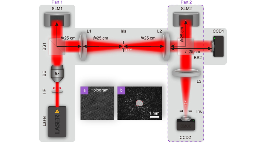
Figure 1 shows the experimental setup for the generation (in Part 1) and measurement (in Part 2) of the complex optical coherence structures of random optical fields. In part 1, a linearly polarized beam with a wavelength λ=632.8 nm is emitted from a He-Ne laser and passes through a half-wave plate (HP). Then, it is expanded by a beam expander (BE) and illuminates a reflective phase-only spatial light modulator (SLM1). We rotated the HP to guarantee that the incident beam on the SLM had horizontal polarization because the SLM1 only responds to this direction. In our experiment, we used the RM or PM superposition principle to generate PCBs with a customized optical coherence structure. To realize the desired mode in the laboratory, the complex amplitude of the RM/PM needed to be encoded [described by T(r) in Eq. (13) or K(r,κmn) in Eq. (14)] into the phase-only SLM. We followed the protocol described by Rosales-Guzmãn and Frobes42, 43 to design the computer-generated holograms (CGHs):

Fig. 1. Schematic of an experimental setup for generation (part 1) and measurement (part 2) of the complex optical coherence structures of random optical fields. (a) Example of the computer-generated holograms loaded on the screen of SLM1, which is used to customize the complex spatial optical coherence structure of the random optical fields. (b) An instantaneous speckle intensity captured by the CCD1 camera, wherein the irregular area denotes an obstacle. HP, half-wave plate; BE, beam expander; BS1 and 2, beam splitters; SLM1 and 2, phase-only spastial light modulators; L1–3, thin lenses with same focal length f=25 cm; CCD1 and 2, charge-coupled devices. The irises are used to select the positive (or negative) 1st diffraction beam; The CCD1 and CCD2 cameras are used to capture the individual mode intensity patterns in the source plane and the Fourier plane, respectively.

下载图片 查看所有图片

ΦSLM(r)=FEsin[Arg[E(r)]+2πfxx],

where E(r) denotes a pre-encoded complex function; and FE is obtained by the numerical inversion of J1(FE)=Abs[E(r)] , where J1 is the first-order Bessel function of the first kind; we applied “Abs” and “Arg” to the function to achieve its amplitude and phase, respectively; and fx represents the grating frequency in the x-direction. The beam reflected by the SLM1 passed through a 4f optical imaging system consisting of the thin lenses L1 and L2. We used an iris in the Fourier plane to select the positive (or negative) 1st diffraction beam, which was the desired mode; we refreshed the CGHs to achieve multiple modes. Based on Eqs. (12–14), we could produce PCBs belonging to either the Schell-model or non-Schell-model type and those with different optical statistics. The beam transmitted through the second beam splitter (BS2) arrived at the charge-coupled device (CCD1). When a mass of the modes were captured, the desired PCBs could be recovered via the mode-superposition principle. In Part 2, the beam reflected by BS2 arrived at SLM2. We followed the same protocol [Eq. (16)] to encode an irregular obstacle, as described by Oi(r),i=1,2,3 , into SLM2. The modulated beam was focused by the thin lens L3 and captured by CCD2. The distance between SLM2 and L3 and that between L3 and CCD2 were the focal lengths of L3. Hence, the CCD2 plane was treated as a Fourier plane. We used an iris to select the positive (or negative) 1st diffraction beams. We captured three intensity profiles using CCD2 via refreshing the CGHs (i.e., the obstacles) in SLM2 and employed Eqs. (4–10) to recover the optical coherence structure. In the following section, we present the obtained simulation and experimental results that demonstrate the validity of our protocol.

We first considered Schell-model PCBs subjected to Gaussian statistics. To illustrate the robustness of this protocol, we followed the RM method [see Eqs. (11–13)] and selected a complex PCB without any analytical expression, where we set the letter “A” as the power spectrum density function P(κ) and K(r,κ)=exp(i2πrκ) . We chose an irregular obstacle [see Fig. 1(b)]. Figure 2 shows the real and imaginary parts of μ(r) and its square of the modulus; the simulation and experimental results are presented in the upper and lower rows, respectively. The perfect agreement between both results demonstrate the validity of our protocol. More importantly, the robust applicability of our method to complex beams and arbitrary obstacles well demonstrates the robustness of our method. Further, to quantify the precision of our proposed protocol, we adopt the widely used structural similarity (SSIM)44 to evaluate the similarity between experimental/simulation results and theoretical results (not shown here to save space). The SSIM falls into the interval [0, 1], and the larger the value, the better the experimental/simulation results. The SSIMs of the real and imaginary parts of simulation and experimental results are very close to 1, as shown in the figures. It demonstrates that our protocol has high precision.

Fig. 2. (ac) Simulation and (df) experimental results for the [(a) and (d)] real part; [(b) and (e)] imaginary part; and the [(c) and (f)] square of the modulus of the optical coherence structure functionμr) of the complex partially coherent beam. The letter “A” is adopted as the power spectrum density function P(κ), and K(r, κ) = exp (−i2πr·κ). Such a partially coherent beam has been produced by the RM method in the experiment, and an irregular obstacle has been chosen, as shown in Fig. 1 (b).

下载图片 查看所有图片

Next, we shall describe how this protocol is also applicable to Schell-model PCBs with non-Gaussian statistics. As suggested by the PM method in Eq. (14), we employed a complex amplitude-modulation encoding algorithm [see Eq. (16)] to produce each PM and then synthesize the PCB. In such a PCB, we adopted an off-axis ellipse band as the power spectrum density function, P(κ) , where it is equal to 1 inside the band and 0 otherwise. The major-to minor-axis ratio was set to 3∶2. The width of the ellipse band was 0.16 mm, and the displacement was 0.8 mm along the horizontal axis. Furthermore, K(r,κ) could be obtained as: K(r,κ)=exp(i2πrκ) . In order to show the differences and similarities between the same PCB but with different optical statistics, we display the experimental results from the above PCBs with Gaussian (produced by the RM method) and non-Gaussian (produced by the PM method) statistics in the upper and lower rows of Fig. 3, respectively. We expected that their individual mode patterns would be different. The patterns of the RM and PM are shown in Fig. 3(a) and 3(e), respectively. Under the RM method, the generated RM obeyed Gaussian statistics, and hence, the intensity probability density function (PDF) obeyed a negative exponent. The experimental results for both space and time are shown in Fig. 3(b). The experimentally obtained intensity PDFs of the PM are shown in Fig. 3(f); they do not yield Gaussian statistics in either space or time. We employed our protocol to recover the optical coherence of the structure; the real and imaginary parts of the optical coherence structures are shown in Fig. 3(c), 3(d), 3(g), and 3(h). Although they had different optical statistics, the results were identical for both beams. This demonstrated that the proposed method would be applicable to PCBs with different optical statistics.
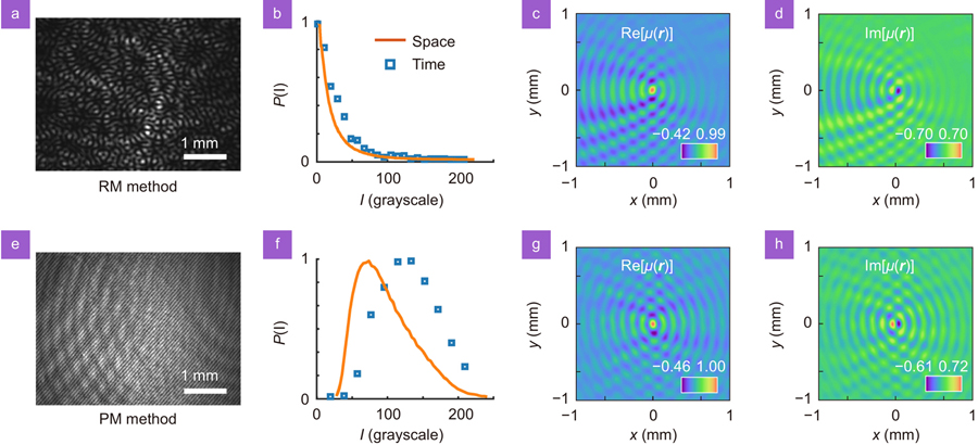
Fig. 3. Experimental results for the same partially coherent Schell-model beams with different optical statistics. In the upper (ad) and lower (eh) rows, they have Gaussian (produced by RM method) and non-Gaussian (produced by PM method) statistics, respectively. (a) and (e) show the individual RM and PM patterns, respectively; (b) and (f) show the experimentally measured intensity PDF curves in space and time. The beam intensity captured by the CCD camera is saved as a grayscale image. The magnitude of grayscale value represents the intensity value of the beam. The spatial intensity PDF is obtained by calculating the gray value of all pixels of a single mode pattern image (consisting of 1288×964 pixels). The temporal intensity PDF is obtained by calculating the gray value of all mode patterns (refreshed by time) at the fixed spatial position; (c, d, g, h) show the experimentally measured real and imaginary parts of the complex optical coherence structures.

下载图片 查看所有图片

For a non-Schell-model PCB, that is, a PCB with a non-uniformly correlated function45, the optical coherence structure is highly sensitive to the reference point position. We applied Eq. (10) and tried to recover the optical coherence structure of the non-Schell-model PCB. Such a beam subjected to non-Gaussian statistics, is chosen as one example. Here, the adopted power spectrum density function is the same as that in Fig. 3, and the kernel function K(r,κ) is given by:

K(r,κ)=exp[i2π(x2κ+y2κ)/4a0],

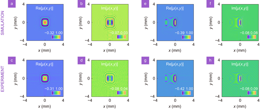
where a0 is constant and assumed to be a0=1m . We followed PM method to produce such a beam. The experimental results for the non-Schell model PCB are shown in Fig. 4. We adopted different reference point positions to show the features of the optical coherence structure with the non-Schell-model type. The simulation and experimental results for the real and imaginary parts of the optical coherence structures are displayed in the upper and lower rows, respectively, in Fig. 4. We adopted the reference point positions r0=(0 mm, 0 mm) and r0 =(1 mm, 0 mm) in Fig. 4(a–d) and 4(e–h), respectively. The distributions of both parts of the optical coherence structures are indeed sensitive to the reference point position r0, showing non-uniform correlation features. Overall, the simulation and experimental results agreed extremely well.

Fig. 4. Simulation (upper row) and experimental (lower row) results for the optical coherence structures of the non-Schell-model partially coherent beams subjected to non-Gaussian statistics, with the reference point positions (ad) r0= (0 mm, 0 mm) and (eh) r0 = (1 mm, 0 mm). In the experiment, such a partially coherent beam has been produced by the PM method, and the Dirac obstacle has been replaced by a circular obstacle with a radius of 0.15 mm.

下载图片 查看所有图片

Finally, we shall show our protocol can be highly used in the optical coherence structure related applications, and can be conducive to rapid improvement of application efficiency. We took one example - optical coherence encryption protocol proposed by Peng et al17. In that work, they used a generalized HBT method for this application, which must take a lot of time for doing speckles statistics to recover a single image. Here we displayed that the proposed protocol can decrypt the dynamic images (or a video). Regarding the encryption technique, they followed Eq. (11); the P(κ) function was plaintext, the K(r,κ) function was the encryption key, and the optical coherence structure was ciphertext. Here, we have reconducted the encryption experiment, setting the dynamic letter “OES” as the P(κ) function and K(r,κ)=exp[i10π(x2+y2)i2π(xκ+yκ)] . We used our protocol to recover the optical coherence structures in the experiment; the obtained three instantaneous real and imaginary parts are shown in the first and second rows in Fig. 5, respectively. The images can be recovered via an inverse fractional Fourier transform of the optical coherence structure17, and the corresponding instantaneous reconstructed images are shown in the bottom row of Fig. 5. The images rotated and shifted, proving that we could decrypt the dynamic images (or videos) encrypted using the optical coherence encryption technique. The processing time of mathematical calculation by software Matlab can be ignored, and the speed of image recovery depends on the refresh rate of the SLM and frame rate of the CCD. In our experiment, the refresh rate of the SLM was 60 Hz, and the frame rate of the CCD was 60 fps. Therefore, we can decrypt the video at ideal 20 fps. We expected to improve the speed of image recovery by adopting a SLM and a CCD with a higher refresh rate and frame rate. Regarding current commercial optical devices, our protocol can recover videos at frame rates of up to 100 fps.
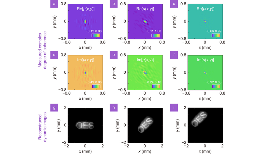
Fig. 5. Experimentally recovered optical coherence structures and decrypted dynamic images. (ac) Real and (df) imaginary parts of the optical coherence structures are reconstructed by our measurement protocol. (gi) Corresponding instantaneous recovered images from the optical coherence structures.

下载图片 查看所有图片

4 Conclusion

In this study, we propose a robust, convenient, and fast technique to measure the optical coherence structures of random optical fields using a classical optical diffraction experiment—the generalized Arago spot experiment. We have provided rigorous mathematical solutions and presented them in extremely simplified analytical expressions based on different beam types; these solutions are applicable to any genuine PCB subjected to different optical statistics. Regarding the Schell-model PCBs common in laboratories, our protocol is valid for any obstacle, regardless of its shape, size, and location. Regarding the non-Schell-model type (i.e., non-uniformly correlated PCBs), the Dirac pinhole was adopted as the obstacle, and the location of the obstacle determined the reference point position of the degree of coherence function. In the experiment, it was necessary to capture the far-zone intensity only three times, and after simple calculations, we could precisely recover the real and imaginary parts of the complex optical coherence structures. The experimental results perfectly agreed with the simulation ones. They well indicate our protocol has simplicity, high efficiency, and precision. We believe that our proposal will shed new light on phase measurement, optical imaging, and other applications.

5 Acknowledgements

This work was supported by the National Key Research and Development Program of China (2022YFA1404800, 2019YFA0705000), National Natural Science Foundation of China (11974218, 12004220, 12104264, 12192254, 92250304), Regional Science and Technology Development Project of the Central Government (YDZX20203700001766), China Postdoctoral Science Foundation (2022T150392), and the Natural Science Foundation of Shandong Province (ZR2021QA014, ZR2021ZD02).

X. Liu and Q. Chen completed the theoretical model and performed the experiments. J. Zeng conducted the analysis and prepared the manuscript. C. H. Liang proposed the original idea. Y. J. Cai supervised the work. All the authors discussed and analyzed the results and commented on the manuscript at all stages.

The authors declare no competing financial interests.

References

[1] Mandel L, Wolf E. Optical Coherence and Quantum Optics (Cambridge University Press, Cambridge, 1995).

[2] Liu YL, Dong Z, Chen YH, Cai YJResearch advances of partially coherent beams with novel coherence structures: engineering and applicationsOpto-Electron Eng20224922017810.12086/oee.2022.220178

[3] Karamata B, Lambelet P, Laubscher M, Salathé RP, Lasser TSpatially incoherent illumination as a mechanism for cross-talk suppression in wide-field optical coherence tomographyOpt Lett20042973673810.1364/OL.29.000736

[4] Dhalla AH, Migacz JV, Izatt JACrosstalk rejection in parallel optical coherence tomography using spatially incoherent illumination with partially coherent sourcesOpt Lett2010352305230710.1364/OL.35.002305

[5] Kang JQ, Zhu R, Sun YX, Li JN, Wong KKYPencil-beam scanning catheter for intracoronary optical coherence tomographyOpto-Electron Adv2022520005010.29026/oea.2022.200050

[6] Ricklin JC, Davidson FMAtmospheric turbulence effects on a partially coherent Gaussian beam: implications for free-space laser communicationJ Opt Soc Am A2002191794180210.1364/josaa.19.001794

[7] Lu XY, Wang ZY, Zhang SX, Konijnenberg AP, Ouyang YQ et alMicroscopic phase reconstruction of cervical exfoliated cell under partially coherent illuminationJ Biophotonics202114e20200040110.1002/jbio.202000401

[8] Lu XY, Shao YF, Zhao CL, Konijnenberg S, Zhu XL et alNoniterative spatially partially coherent diffractive imaging using pinhole array maskAdv Photonics2019101600510.1117/1.AP.1.1.016005

[9] Anand V, Han ML, Maksimovic J, Ng SH, Katkus T et alSingle-shot mid-infrared incoherent holography using Lucy-Richardson-Rosen algorithmOpto-Electron Sci2022121000610.29026/oes.2022.210006

[10] Schneider R, Mehringer T, Mercurio G, Wenthaus L, Classen A et alQuantum imaging with incoherently scattered light from a free-electron laserNat Phys20181412612910.1038/nphys4301

[11] Dravins D, Lagadec T, Nuñez PDOptical aperture synthesis with electronically connected telescopesNat Commun20156685210.1038/ncomms7852

[12] Liang CH, Monfared YE, Liu X, Qi BX, Wang F et alOptimizing illumination’s complex coherence state for overcoming Rayleigh’s resolution limitChin Opt Lett20211905260110.3788/COL202119.052601

[13] Batarseh M, Sukhov S, Shen Z, Gemar H, Rezvani R et alPassive sensing around the corner using spatial coherenceNat Commun20189362910.1038/s41467-018-05985-w

[14] Liu YL, Chen YH, Wang F, Cai YJ, Liang CH et alRobust far-field imaging by spatial coherence engineeringOpto-Electron Adv2021421002710.29026/oea.2021.210027

[15] Liu YL, Zhang X, Dong Z, Peng DM, Chen YH et alRobust far-field optical image transmission with structured random light beamsPhys Rev Appl20221702404310.1103/PhysRevApplied.17.024043

[16] Pan RX, Liu X, Tang JH, Ye H, Liu ZZ et alEnhancing the self-reconstruction ability of the degree of coherence of a light beam via manipulating the cross-phase structureAppl Phys Lett202111911110510.1063/5.0063939

[17] Peng DM, Huang ZF, Liu YL, Chen YH, Wang F et alOptical coherence encryption with structured random lightPhotoniX20212610.1186/s43074-021-00027-z

[18] Liang CH, Wang F, Liu XL, Cai YJ, Korotkova OExperimental generation of cosine-Gaussian-correlated Schell-model beams with rectangular symmetryOpt Lett20143976977210.1364/OL.39.000769

[19] Cai YJ, Chen YH, Wang FGeneration and propagation of partially coherent beams with nonconventional correlation functions: a review [Invited]J Opt Soc Am A20143120832096

[20] Hyde IV MW, Bose-Pillai S, Voelz DG, Xiao XFGeneration of vector partially coherent optical sources using phase-only spatial light modulatorsPhys Rev Appl2016606403010.1103/PhysRevApplied.6.064030

[21] Voelz D, Xiao XF, Korotkova ONumerical modeling of Schell-model beams with arbitrary far-field patternsOpt Lett20154035235510.1364/OL.40.000352

[22] Zhu SJ, Li P, Li ZH, Cai YJ, He WJGenerating non-uniformly correlated twisted sourcesOpt Lett2021465100510310.1364/OL.442264

[23] Wang F, Lv H, Chen YH, Cai YJ, Korotkova OThree modal decompositions of Gaussian Schell-model sources: comparative analysisOpt Express202129296762968910.1364/OE.435767

[24] Ponomarenko SAComplex Gaussian representation of statistical pulsesOpt Express201119170861709110.1364/OE.19.017086

[25] Divitt S, Novotny LSpatial coherence of sunlight and its implications for light management in photovoltaicsOptica201529510310.1364/OPTICA.2.000095

[26] González AI, Mejía YNonredundant array of apertures to measure the spatial coherence in two dimensions with only one interferogramJ Opt Soc Am A2011281107111310.1364/JOSAA.28.001107

[27] Partanen H, Turunen J, Tervo JCoherence measurement with digital micromirror deviceOpt Lett2014391034103710.1364/OL.39.001034

[28] Mendlovic D, Shabtay G, Lohmann AW, Konforti NDisplay of spatial coherenceOpt Lett1998231084108610.1364/OL.23.001084

[29] Halder A, Partanen H, Leinonen A, Koivurova M, Hakala TK et alMirror-based scanning wavefront-folding interferometer for coherence measurementsOpt Lett2020454260426310.1364/OL.398704

[30] Bhattacharjee A, Aarav S, Jha AKTwo-shot measurement of spatial coherenceAppl Phys Lett201811305110210.1063/1.5041076

[31] Tran CQ, Williams GJ, Roberts A, Flewett S, Peele AG et alExperimental measurement of the four-dimensional coherence function for an undulator x-ray sourcePhys Rev Lett20079822480110.1103/PhysRevLett.98.224801

[32] Cho S, Alonso MA, Brown TGMeasurement of spatial coherence through diffraction from a transparent mask with a phase discontinuityOpt Lett2012372724272610.1364/OL.37.002724

[33] Wood JK, Sharma KA, Cho S, Brown TG, Alonso MAUsing shadows to measure spatial coherenceOpt Lett2014394927493010.1364/OL.39.004927

[34] Shao YF, Lu XY, Konijnenberg S, Zhao CL, Cai YJ et alSpatial coherence measurement and partially coherent diffractive imaging using self-referencing holographyOpt Express2018264479449010.1364/OE.26.004479

[35] Wang ZY, Lu XY, Huang WR, Konijnenberg AP, Zhang H et alMeasuring the complete complex correlation matrix of a partially coherent vector beam via self-referencing holographyAppl Phys Lett202111911110110.1063/5.0061838

[36] Liu XL, Wang F, Liu L, Chen YH, Cai YJ et alComplex degree of coherence measurement for classical statistical fieldsOpt Lett201742778010.1364/OL.42.000077

[37] Huang ZF, Chen YH, Wang F, Ponomarenko SA, Cai YJMeasuring complex degree of coherence of random light fields with generalized Hanbury Brown-Twiss experimentPhys Rev Appl20201304404210.1103/PhysRevApplied.13.044042

[38] Rennie R. A Dictionary of Physics 7th ed (Oxford University Press, New York, 2015).

[39] Ma PJ, Kacerovská B, Khosravi R, Liang CH, Zeng J et alNumerical approach for studying the evolution of the degrees of coherence of partially coherent beams propagation through an ABCD optical systemAppl Sci20199208410.3390/app9102084

[40] Shen YC, Sun H, Peng DM, Chen YH, Cai QL et alOptical image reconstruction in 4f imaging system: Role of spatial coherence structure engineeringAppl Phys Lett202111818110210.1063/5.0046288

[41] Schmidt JD. Numerical Simulation of Optical Wave Propagation with Examples in MATLAB (SPIE, Bellingham, 2010).

[42] Rosales-Guzmán C, Forbes A. How to Shape Light with Spatial Light Modulators (SPIE, Bellingham, 2017).

[43] Liu X, Monfared YE, Pan RX, Ma PJ, Cai YJ et alExperimental realization of scalar and vector perfect Laguerre–Gaussian beamsAppl Phys Lett202111902110510.1063/5.0048741

[44] Wang Z, Bovik AC, Sheikh HR, Simoncelli EPImage quality assessment: from error visibility to structural similarityIEEE Trans Image Process20041360061210.1109/TIP.2003.819861

[45] Yu JY, Cai YJ, Gbur GRectangular Hermite non-uniformly correlated beams and its propagation propertiesOpt Express201826278942790610.1364/OE.26.027894

Xin Liu, Qian Chen, Jun Zeng, Yangjian Cai, Chunhao Liang. Measurement of optical coherence structures of random optical fields using generalized Arago spot experiment[J]. Opto-Electronic Science, 2023, 2(2): 220024.

引用该论文: TXT   |   EndNote

相关论文

加载中...

关于本站 Cookie 的使用提示

中国光学期刊网使用基于 cookie 的技术来更好地为您提供各项服务,点击此处了解我们的隐私策略。 如您需继续使用本网站,请您授权我们使用本地 cookie 来保存部分信息。
全站搜索
您最值得信赖的光电行业旗舰网络服务平台!