Optimizing depth of field in 3D light-field display by analyzing and controlling light-beam divergence angle
1. Introduction
3D light-field display (LFD) can restore original light-field distribution of a real 3D scene[1–6], which is regarded as an ideal and potential 3D display technology and can be better applied in many fields, especially for medical research, museum exhibitions, and military command.
In the early stages of light-field theory, the plenoptic function (a 7D function that describes light in a scene from position, angle, wavelength, and time) was used to model the distribution of light rays[7]. For practical applications, the light-field model has been simplified to five dimensions[8]. This 5D model can effectively represent the set of light rays emanating from every point in 3D space in every direction, where the light rays at every possible location are denoted by and from every possible angle by . As shown in Fig. 1, the real scene can be interpreted as a combination of voxels , and the corresponding light field can be parameterized as . To obtain such a light field, a 2D display device (such as an LCD, LED, or projector) is utilized to provide up to 2D location information , while a light control device comprising a series of light control units is employed to provide up to 2D directional information . Consequently, the 3D reconstructed scene can be interpreted as a combination of reconstructed voxels , which only contains light ray information in four dimensions, and the corresponding reconstructed light field can be parameterized as .

Fig. 1. 3D light field reconstruction process of the real scene and contrast at different DOF.
Depth of field (DOF) is defined as the range of depth within which a 3D image can be accurately reconstructed. Due to the lack of z dimension in the reconstructed light field, the DOF of the restored 3D scene is quite limited. In particular, the viewing disparity is proportional to the DOF in the 3D display, and more serious image aliasing usually occurs when the DOF exceeds a certain threshold, which degrades the imaging quality and lowers the visual experience. As shown in Fig. 1, at a depth of 5 cm, the viewing disparity is very minimal; thus the image is clear and acceptable. However, at a depth of 20 cm, image quality deteriorates dramatically, and depth information cannot be accurately expressed. Therefore, the key challenge facing 3D LFD is to develop effective methods to improve the DOF of 3D reframing scene.
In order to design a high-quality 3D LFD system, a number of studies about DOF analysis and promotion were performed[9–14]. Some researchers analyze the light intensity distribution in the amplitude-modulating pickup system and implement an optical pickup experiment using an amplitude-modulated sensor array (SA) to generate the DOF-enhanced elemental image array (EIA) for computational reconstruction to produce the 3D images with extended DOF[9]. This method is more suitable for enhancing the DOF of 3D scenes with small depth ranges. In another study, a gradient-amplitude-modulating (GAM) method was proposed to enhance DOF in an II pickup system[10]. However, the GAM method sacrifices light efficiency and may not be practical in scenarios with strict optical efficiency requirements. Adjusting lens parameters has also been attempted to overcome DOF limitations[11–14], but this approach still suffers from degradation of light efficiency and information quantity.
Here, the divergence angle of a light beam (DALB) emitted from each light control unit and corresponding to different subpixel units is considered to be a crucial factor influencing DOF in 3D LFD. The present study examines the impact of DALB on DOF and proposes an optimization scheme that enhances DOF and ensures the display quality from different viewing perspectives.
2. Analysis
2.1. Relation between DALB and DOF
In the light-field reconstruction process, the intensity and color information of the voxels are loaded onto the subpixels of the LCD panel, while the direction and location information are provided by the light control panel. In the ideal theoretical analysis process of voxel reconstruction, the chief rays emitted from the center of subpixels a1 to an converge in the free space after passing through the corresponding light control units so that a point-like voxel “” is reconstructed. This analysis method, which only considers the chief rays, has been widely used in voxel analysis of 3D-LFD[15–20]. However, the actual light path reveals that it is not only the chief ray that participates in voxel generation. Due to the fact that the subpixels emit rays from any position, a light beam (LB) will be generated by the light modulation of light control units. As a result of this phenomenon, the actual constructed voxel is not point-like but spot-like, as illustrated in Fig. 2. Considering the minimum angular resolution of human eyes, when the diameter of speckles is less than a certain value, it can be recognized as a clear image point; otherwise, aliasing appears and affects the reconstruction quality, particularly by damaging the depth perception.
The DOF is the range of distances in which speckles of voxels can be distinguished from one another and objects can be imaged with clarity. Due to the fact that the diameter of the voxel speckle varies with the DALB, the DOF is in turn affected. As shown in Fig. 2, the reconstruction voxel is regarded as an example to demonstrate how the DALB affects the DOF of the LFD system.
In Fig. 2, a set of LBs from display pixels are focused on the depth plane of voxel by the light control panel, forming a spot with a diameter of , and the chief rays of the beams converge at point A. This light-control panel is located at the coordinate plane, and the center of voxel is located at the coordinate axis. These LBs are denoted by , respectively, where represents their number. is one LB to be modulated, the lateral distance between the center of its corresponding light control unit and the center of the voxel is called , and its corresponding DALB is called . According to the geometrical relationship in Fig. 3,

Fig. 3. (a) Optical path at 0° incidence angle without aberration; (b) optical path at 0° incidence angle in actual situations; (c) intensity distribution of ideal lens and actual lens at 0° incidence angle; (d) variation in DALB with increasing incidence angle.
In these equations, is the diameter of the voxel , which is an acceptable size to be able to form clear reconstructed images. is the viewing angle of the voxel . is the distance from the voxel to the light-control panel, which can reflect the DOF of the light field. According to the fact that is usually much larger than for a better stereo experience, further derivation of Eqs. (1) and (2) can be obtained,
Afterwards, can be deduced based on the above results and approximately expressed as a function of ,
The derived formula shows that the DOF of the reconstructed light field is inversely proportional to the DALB. It follows that diminishing DALB can elevate the DOF of the 3D light field.
2.2. Influencing factors of DALB in a lens-based 3D-LFD system
With the relation between DOF and DALB now ascertained, it becomes necessary to discuss the factors that impact DALB.
Lens array is an established solution as a light-control panel for light controlling. One of the basic optical properties of the lens element is the aberration characteristics, which causes the emergent light rays to deviate from their anticipated path. Thus, aberrations must be considered in angular analysis. In the upcoming section, the optical path of the lens unit will be employed to demonstrate how aberrations impact DALB in a lens-based 3D-LFD system.
Figures 3(a) and 3(b) show the optical path of an ideal lens unit and an actual lens unit when the direction of the LB is 0°. Here, the direction of the LB refers to the angle between the subpixel’s chief ray and the center of the corresponding lens unit. The spacing between the subpixel unit and the lens unit is set to the focal length of the lens unit, denoted by . Under an aberration-free situation, the LB emitted from a subpixel will diffuse at an angle of after passing through an ideal lens element, as depicted in Fig. 3(a). However, the DALB is highly vulnerable to aberrations in practical applications. As shown in Fig. 3(b), due to the presence of aberrations in the lens elements, this angle will expand by a certain amount to . Furthermore, the light-intensity distribution in Fig. 3(c) also suggests that the existence of lens aberrations significantly increases DALB. In the above experiment, the aperture and focal length of the lens unit are 10 and 20 mm, respectively, and the size of the subpixel is 2 mm.
Snell’s law dictates that aberrations become more severe for light rays with larger incident angles. Thus, the direction of an LB also affects its divergence angle, as evidenced by the analysis above. Figure 3(d) illustrates the tendency of a DALB going through an ideal lens unit and an actual lens unit at different directions. With an increase in the direction angle, corresponding to an ideal lens is on the decline, down from 5.72° to 4.64°, while corresponding to an actual lens is on the rise, up from 10.81° to 19.71°. Moreover, of the actual lens consistently surpasses that of the ideal lens. In Section 2.1, it is concluded that an increase in the DALB leads to decreased DOF, thereby impairing depth perception and damaging the visual experience at large viewing angles.
According to the theory of optical aberrations, when the direction angle increases, the influence of spherical, chromatic aberrations is small; however, coma, astigmatism, and field curvature become more serious.
In order to investigate the effects of coma, astigmatism, and field curvature on a DALB, aberration simulation experiments were conducted. Zernike polynomials are commonly employed to characterize the wavefront aberrations of optical systems. Therefore, specific aberrations were simulated by introducing Zernike coefficients onto an ideal lens and subsequently modeled in Zemax (optical simulation software). The angles of the DALB were measured using the RAID evaluation function operands at different angles.
Figure 4 presents the results of the aberration simulation experiments, illustrating the individual effects of three types of aberrations on the DALB. represents the difference between the DALBs of actual and ideal lenses, i.e., . It can be indicated that the value for each of the three aberrations is always greater than 0°, and with an increase in incident angle, all three aberrations cause to rise, with field curvature having the most significant effect.
3. Optimization Method
Based on the analysis above, the imaging quality of the lens unit emerges as a crucial factor for reconstructing high-quality 3D light fields with a small DALB and a large DOF. In the subsequent discussion, the maximum incident angle is designed to be 50° (whole angle 100°). Under this situation, when using a single-lens unit, the resulting DALB will be extremely large and significantly impair the depth quality of the 3D image. For this reason, it becomes imperative to implement an aberration-limited lens structure with suppressed coma, astigmatism, and field curvature while prioritizing maximum optimization weight for the field curvature.
In classical optical design, a symmetrical-lens structure is employed to suppress field curvature, and a combination structure of lens and aperture stop serves to suppress coma and astigmatism. Additionally, the aberration theory stipulates that a reduced optical aperture of the lens can further eliminate the three kinds of aberrations. Taking these factors into account, an initial structure of the optimized compound lens is obtained, as shown in Fig. 5. This structure is composed of lens-1, lens-2, and an aperture stop, with lens-2 and the aperture stop aimed at suppressing coma and astigmatism, and lens-1 tasked with suppressing the field curvature. To enhance the effect of inhibiting aberrations, both lens-1 and lens-2 utilize smaller optical apertures.

Fig. 5. Three optimized optical structures and the initial structure of the compound lens.
In order to minimize the impact of aberrations, we introduced aspheric models on the two surfaces to suppress coma and astigmatism while balancing the higher-order aberrations. The aspheric surface formula is given in Eq. (5),
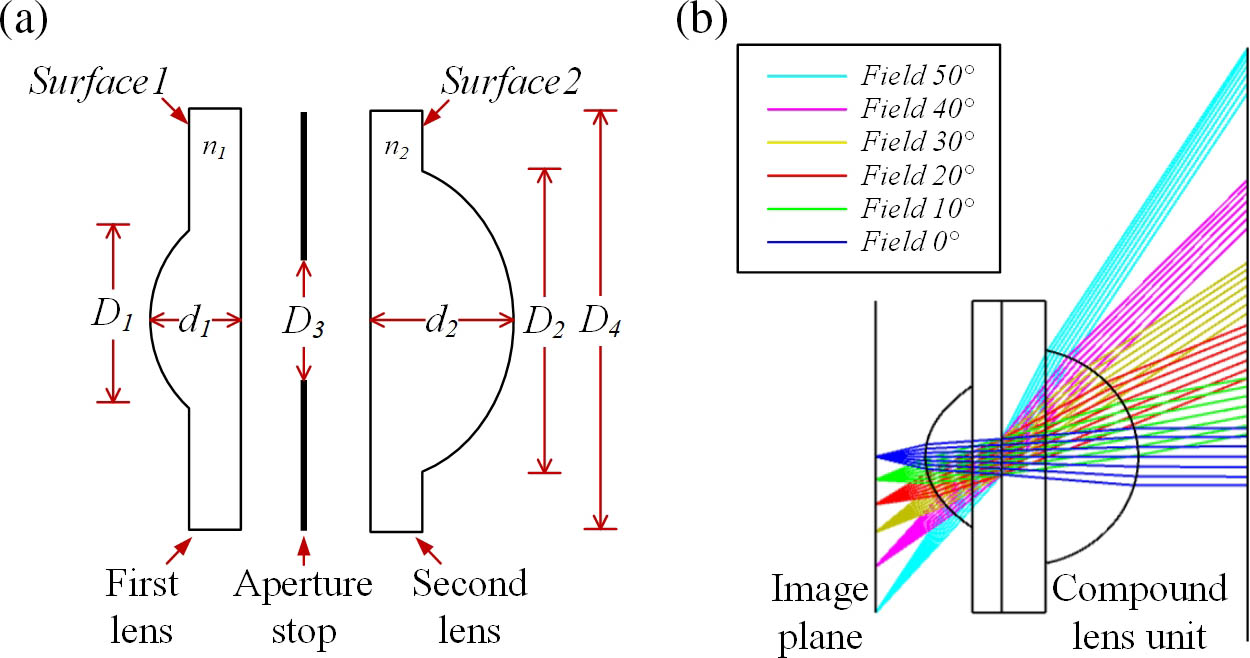
Fig. 6. Design of the optimized compound lens. (a) Parameter description; (b) light-path distribution.
Table 1. Structural Parameters for the Optimized Compound Lens
|
Table 2. Aspheric Parameters of Lens Surface
|
Figure 6(b) illustrates the simulation results for the corrected light distribution based on the optimized compound lens elements. (Given the symmetry of the system, we only present one side of the viewing range for clarity.) We can see that, after optimization, the emergent LBs exhibit a nearly parallel distribution and hardly change with field of view.
To validate the effectiveness of the proposed method in reducing the DALB, a simulation experiment was conducted using a subpixel size of 0.06 mm (which is commonly used for one subpixel in a 65-inch 8K monitor) as an example. Five different lenses were simulated and modeled, including an ideal lens, a compound lens, and standard lenses with diameters of 100%, 30%, and 20%, respectively. The curve of the DALB with respect to the incident angle for these lenses is shown in Fig. 7.

Fig. 7. Change in the DALB of different incident angles of five kinds of lenses with the subpixel size of 0.05 mm in the (a) central viewing area and (b) peripheral viewing area.
In the central viewing area from 0° to 25°, the optimized compound lens consistently exhibited lower DALB compared to the standard lenses, and its DALB distribution closely resembled that of the ideal lens. It should be noted that the standard lens with 100% diameter theoretically achieves the same 100° viewing angle as the compound lens. However, due to its large curvature, it introduces severe aberrations that make accurate DALB measurement unfeasible. The standard lenses with 30% and 20% diameters sacrifice viewing angle to reduce the DALB, but the difference from the compound lens remains substantial.
In the peripheral viewing area from 25° to 50°, the optical performance of all standard lenses deteriorates significantly, whereas the optimized compound lens maintains high-quality light control.
In practical engineering applications, standard lenses have a limited capability to achieve a wide viewing angle, and they cannot provide clear display at 100°. In contrast, the proposed compound lens, with its unique optical design, shows significant improvement in reducing the DALB compared to standard lenses, which was previously unattainable.
4. Experiment
To verify the feasibility of the proposed method, the compound lens array is fabricated utilizing the UV embossing process, and the 3D LFD system based on this array is established for experimental validation. The manufactured compound lens array is demonstrated in Fig. 8(b), while the configuration of the experimental 3D LFD system is exhibited in Fig. 8(a). Due to the limitations of manufacturing precision, there may be slight but acceptable deviations between the width of the manufactured compound lens and its design value.
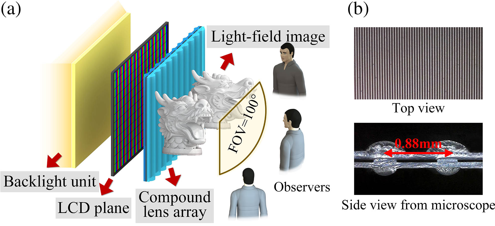
Fig. 8. (a) Configuration of the experimental 3D LFD system; (b) structural diagram of the proposed compound lens array.
Due to the presence of an aperture stop in the proposed compound lens, it inevitably reduces the light efficiency (measured at about 16%) and subsequently lowers the image brightness. To compensate for the brightness loss, the constructed optical system incorporates a high-intensity backlight of 40,000 nits, resulting in a final display brightness of 320 nits, which is considered suitable for most environments, effectively addressing the issue of optical efficiency loss.
In the experimental 3D LFD system, the horizontal viewing angle ranges from to 50°. A 65-inch flat panel LCD device with a resolution of is used to load the synthetic images, constructed using the method proposed by Yu et al.[21]. Placing the novel compound lens array at a distance of 0.5 mm in front of the display device, the constituted 3D image can be observed by observers when displaying the coded image on the LCD panel. The corresponding experimental dimension parameters of the 3D LFD system are listed in Table 3.
Table 3. Dimension Parameters of the 3D LFD System
|
To validate the effectiveness of our proposed methods for aberration suppression and depth enhancement, we conducted a comparative experiment by displaying 3D images on two 3D LFD systems: one with the traditional single-lens array and the other with the newly proposed DALB-limited compound lens array. A model of two dragon sculptures with the theoretical depth of 30.35 cm is captured by 80 virtual cameras, coded, and loaded onto the LCD panel, which was then taken at a distance of 2 m using a Canon camera. The comparison results for different horizontal views are illustrated in Fig. 9 and Visualization 1. By enlarging the 3D image at viewing angles of 0°, 50°, and , we can see that the redesigned system produced clearer reconstructed images and offered more detailed depth information after the DALB had been reduced, especially for the edge perspective. These findings confirm that the proposed light-field display method is capable of facilitating the 3D imaging quality.
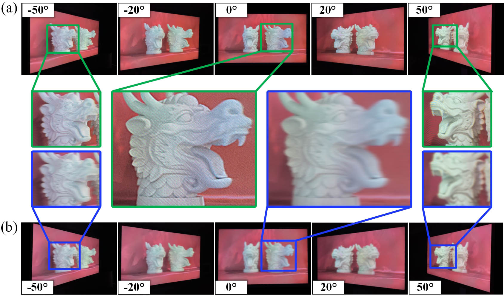
Fig. 9. Comparison of different views of the displayed 3D effects based on (a) the proposed DALB-limited compound lens array (see Visualization 1 ) and (b) the traditional single-lens array.
To quantify the improvement of the DOF after limiting the DALB, a depth verification experiment is then carried out. The main parameters and 3D scene layout are shown in Fig. 10(a). More specifically, the experimental 3D scene features eight letters “A” and “B” placed at equal intervals but at unequal depths. The letter A denotes an object inside the screen, while the letter B represents an object outside the screen. The DOF range of the 3D scene was set from 0 to 30 cm.
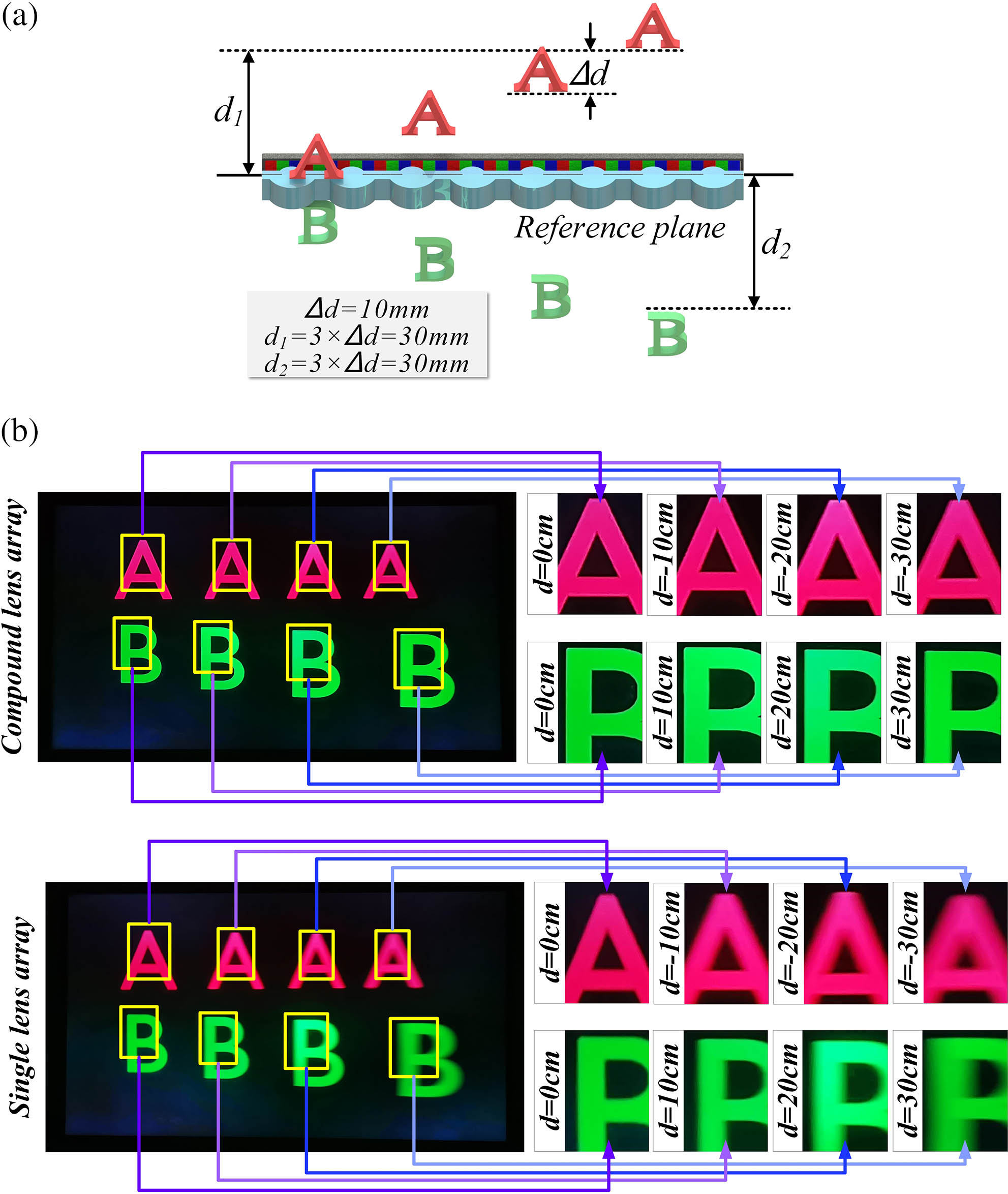
Fig. 10. Confirmation experiments of DOF. (a) Arranged 3D scene; (b) displayed light-field image based on single-lens array and proposed compound lens array.
Figure 10(b) presents the restored light-field images displayed on the 3D LFD system based on the single-lens array and proposed compound lens array, respectively. Comparison of the images shows that the proposed system significantly improves image quality at each depth, particularly when the depth is 30 cm. As seen in the proposed system, letters can be clearly focused, whereas the profile of letters in the comparison system is blurred. These optical experimental results prove that our proposed method of reducing the DALB can obtain a larger DOF, and the 3D LFD system consisting of the designed DALB limited optical structures is particularly suitable for displaying 3D scenes with a large depth.
5. Conclusion
In this paper, a novel DOF analytical approach based on the DALB in a 3D LFD system is proposed. A mathematical model is established to analyze the relationship between the DALB and DOF, and a conclusion that they are inversely proportional is drawn. According to optical path simulation, the expansion of the DALB in standard lenses is attributed to optical aberrations, particularly coma, astigmatism, and field curvature. In order to improve depth quality, a novel compound lens with a two-tier aspherical lens and slit aperture is designed and tested to restrain these aberrations and reduce the DALB diffusion. A 3D LFD system based on the proposed compound lens array is established for experimental validation. The validity of our proposed methods was demonstrated through depth verification experiments. Compared to the 3D images reconstituted by conventional single-lens-based 3D display systems, the proposed DALB-limited 3D display achieved a larger DOF and improved 3D imaging quality. Using the experimental display system, a clear 3D image with a DOF of 30.35 cm within a range of 100° can be viewed.
Article Outline
Xunbo Yu, Yiping Wang, Xin Gao, Hanyu Li, Kexin Liu, Binbin Yan, Xinzhu Sang. Optimizing depth of field in 3D light-field display by analyzing and controlling light-beam divergence angle[J]. Chinese Optics Letters, 2024, 22(1): 011101.


