中国激光, 2021, 48 (19): 1918003, 网络出版: 2021-09-29
基于超构表面的多维光场感知  下载: 2853次
Multidimensional Light Field Sensing Based on Metasurfaces
图 & 表
图 1. 超构表面实现集成化的光谱、偏振、深度感知
Fig. 1. Metasurfaces for integrated spectrum, polarization and depth sensing
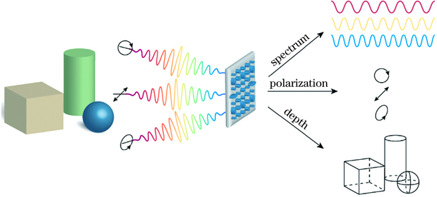
图 2. 可调谐型微型光谱仪。(a)可调谐液晶-亚波长谐振光栅滤波器的示意图[43];(b)在不同电压下测得的滤波器的光学透射率[43];(c)通过激光脉冲照射GST超构表面,致其发生相变示意图[42];(d)GST超构表面随泵浦光光率变化的透射光谱响应[42]
Fig. 2. Tunable micro spectrometer. (a) Schematic of a tunable liquid crystal-subwavelength resonant grating filter[43]; (b) measured optical transmittance of the tunable filter at different applied voltages to liquid crystal cell[43]; (c) schematic of phase change in GST induced by laser irradiation on the GST-based metasurface[42]; (d) transmittance of a GST metasurface as a function of the pump laser fluence[42]

图 3. 阵列型超构表面微型光谱仪。(a)阵列型超构表面微型光谱仪系统示意图;(b)等离激元滤波片阵列的示意图,右下是扫描电子显微镜(SEM)图像和白光照射的光学显微镜图像[49] ;(c)红绿蓝(RGB)滤光片的实验透射光谱[49];(d)具有梯度光栅周期的介质光栅示意图[53];(e)制作的100个宏像素的超构表面阵列的光学图像[54];(f)21个选定宏像素的归一化反射光谱[54]
Fig. 3. Micro spectrometer of metasurfaces array. (a) Schematic diagram of micro spectrometer system of metasurfaces array; (b) schematic diagram of a plasmon filter array, in which the bottom right figure is an SEM image and an optical microscope image illuminated by white light[49]; (c) experimental transmission spectra for the red, green and blue (RGB) filters[49]; (d) schematic of a dielectric grating with gradient grating period[53]; (e) optical images of the fabricated 100-metapixel metasurface[54]; (f) normalized reflectance spectra for selected 21 metapixels[54]

图 4. 窄带滤波响应探测器。(a)等离激元纳米颗粒石墨烯探测器的示意图[58];(b)直径100 nm的纳米盘阵列的SEM图像[58];(c)具有不同尺寸纳米盘阵列的石墨烯探测器的光谱响应[58];(d)在具有2 nm Ti黏附层的n型硅底上的金光栅的示意图[59];(e)金光栅结构的SEM图像[59];(f)响应度峰值随着光栅缝隙距离D的增加而红移(T=200 nm, W=250 nm) [59];(g)等离激元-热释电装置示意图[60];(h)调节金孔尺寸得到的吸收光谱[60];(i)在多晶AlN热释电层上沉积等离激元超表面的垂直探测器结构示意图[61];(j)Au参考探测器和三个超构表面热电感知器的反射光谱和图像[61]
Fig. 4. Narrowband filter response detector. (a) Schematic illustration of the graphene detectors with plasmonic nanoparticles[58]; (b) SEM image of a representative device with the 100-nm diameter nanodisk array[58]; (c) corresponding spectral response of graphene photodetectors with nanodisk arrays of different sizes[58]; (d) schematic of a gold grating on an n-type silicon substrate with a 2-nm Ti adhesion layer[59]; (e) SEM image of gold grating structure[59]; (f) responsivity peaks redshift with increasing grating interslit distance D(T=200 nm, W=250 nm) [59]; (g) schematic diagram of the plasmonic-pyroelectric device[60]; (h) absorption spectrum obtained by adjusting the size of gold pores[60]; (i) schematic of the vertical detector structure with a plasmonic metasurfaces deposited on a polycrystalline AlN pyroelectric layer[61]; (j) reflection spectrum and image of three metasurfaces-pyroelectric detectors and Au reference detector[61]

图 5. 计算型微型光谱仪。(a)计算型光谱仪重构过程示意图;(b)等离激元超构表面滤光片阵列示意图[68];(c)聚乙烯的重构透射光谱[68];(d)光子晶体滤波片阵列的示意图,右上插图为制成的6×6光子晶体结构的光学图像[69];(e)两个发光二极管(绿色和红色)组合的发射光谱[69];(f)3个选定的超构表面单元的SEM图像和光谱[70];(g)使用普通彩色相机和超光谱相机(黑白)拍摄的水果照片,选择5个单波长光谱图像进行重建[70]
Fig. 5. Computational micro spectrometer. (a) Schematic diagram of the reconstruction process of the computational spectrometer; (b) schematic of the plasmonic metasurfaces filter array[68]; (c) reconstructed transmission spectra of polyethylene[68]; (d) schematic of the photonic crystals filer array, in which the upper right figure is the optical image of the fabricated 6 × 6 photonic crystal structures[69]; (e) emission spectrum of a combination of two light-emitting diodes (green and red) [69]; (f)SEM images and spectra of three selected metasurfaces units[70]; (g) photos of fruits captured using an ordinary color camera and our ultraspectral camera (black-and-white), and five single wavelength spectral images are selected to reconstruct[70]

图 6. 光栅型偏振测量超构表面。(a)基于几何相位的GSPM示意图[75];(b)不同波长的LCP和RCP光束入射GSPM后的反射功率随反射角变化的实验结果[75];(c)全Stokes参量测量GSPM光栅的工作原理示意图[77];(d)实验测得的偏振态(实心圆标示)与在庞加莱球主轴上的偏振态(星号标示)对比[77];(e)二维光栅型偏振成像超构表面的一个结构单元[81];(f)光栅型偏振成像超构表面获得的偏振图像[81]
Fig. 6. Grating metasurface polarimeters. (a) Illustration of the geometric phase GSPM[75]; (b) reflected power for LCP and RCP incident beams at different wavelengths as a function of reflected angle after passing through GSPM in the experiment[75]; (c) illustration of the full-Stokes GSPM grating’s measurement principle[77]; (d) measured diffraction contrasts (denoted by filled circles) for polarization states along the main axes of the Poincaré sphere (indicated by asterisks)[77]; (e) a unit cell of the 2D grating metasurface for polarization imaging[81]; (f) polarization images required by the grating metasurface for polarization imaging[81]

图 7. 波导型偏振测量超构表面。(a)波导GSPM结构单元示意图(左)和三种波导GSPM组合的俯视图[85];(b)不同偏振态入射光激发的SPP强度分布[85];(c)散射天线阵列示意图(左),天线阵列偏振测试光路(中),耦合光栅的相机图像显示四个偏振分量被耦合光栅散射(右)[86];(d)基于硅波导和耦合天线的偏振测量示意图以及测量偏振分量在庞加莱球上的表示(左),偏振测量结果(右)[87]
Fig. 7. Waveguide metasurface polarimeters. (a) Sketch of the unit cell of a waveguide GSPM (left) and top view of three combined waveguide GSPMs (right)[85]; (b) color map of the SPP intensity distribution excited by the incident light with different states of polarization[85]; (c) illustration of scattering antenna arrays (left), setup for characterizing the antenna array polarimeter (middle), and camera image of the outcoupling gratings, showing polarization-dependent intensities scattered by the four outcoupling gratings[86]; (d) illustration of polarimeter based on silicon waveguide and the coupling antenna, the measured polariztion states shown in the Poincaré sphere (left), the retrieved polarization states (right)[87]

图 8. 超透镜型偏振测量超构表面[90,93-94]。(a)DoFP超透镜单元的SEM图(上),单元每一部分的偏振基矢用彩色箭头表示(比例尺:1 μm);DoFP超透镜的工作原理示意图(下);(b)目标偏振掩模版(比例尺:100 μm);(c)利用传统方法获得的掩模版的偏振图像(比例尺:100 μm);(d)利用DoFP超透镜获得的相同掩模版的偏振图像(比例尺:100 μm);(e)广义Hartmann-Shack超透镜阵列的系统示意图;(f)径向偏振光束的焦斑强度分布,箭头定性表示局部的偏振态(比例尺:50 μm);(g)超透镜阵列获取的径向偏振光束的焦斑图像;(h)利用超透镜阵列获取的偏振态分布图;(i)PMT超构表面实现矢量光束的自旋、轨道角动量的同时测量
Fig. 8. Metalens metasurface polarimeters[90,93-94]. (a) SEM image of a fabricated DoFP metalens unit cell (upper), in which the polarization basis for each part is shown with the colored arrows and scale bar is 1 μm, and illustration of the DoFP metalens’ working principle (lower); (b) target polarization mask (scale bars:100 μm); (c) fabricated mask imaged using conventional polarimetry(scale bars:100 μm); (d) the same mask imaged using the DoFP metalens(scale bars:100 μm); (e) scheme of the generailzed Hartmann-Shack metalens array; (f) intensity distribution of the focal spot for a radially polarized incident beam, in which the arrows qualitatively indicate the local polarization states and scale bar is 50 μm; (g) image of the focal spot from the metalens array for the radially polarized beam; (h) polarization profile obtained from the metalens array; (i) metasurface-based PMT for simultaneous detection of spin and orbital angular momenta

图 9. 分时型偏振测量超构表面[95]。(a)GIAM偏振测量的原理图,以及GIAM的扫描电镜显微图;(b)电压值Vg为0时入射光沿x轴偏振(方块),以及三个电压值下入射光沿y轴(圆)偏振的反射谱(Rxx(yy) = |rxx(yy)|2),垂直虚线对应工作波长为6.7 μm;(c)四种偏振态入射下测得的反射光强度(左;绿:RCP;蓝:LCP;紫:x偏振;红:椭圆偏振);GIAM测得的偏振态(虚线)与旋转分析仪测得的偏振态(实线)的对比(右)
Fig. 9. Division-of-time metasurface polarimeters[95]. (a) Schematic of the GIAM-based polarimeter and the SEM image of the fabricated GIAM; (b) reflectivity spectra (Rxx(yy) = |rxx(yy)|2) for the incident light polarized along the y-axis (circles) at three values of Vg, and along the x-axis (squares) at Vg=0 V, in which vertical dotted line corresponds to wavelength of operation λ0=6.7 μm; (c) measured intensities (left) of the reflected light at the detector measured for the four incident polarization states (Green, near-RCP; blue, near-LCP; purple, near-x-polarized; red, elliptical polarization), and comparison (right) between the polarization states obtained from the GIAM polarimetry (dashed lines) and those obtained from the rotating analyzer polarimetry (solid lines)

图 10. 探测器集成型偏振测量超构表面。(a)集成6组不同等离激元狭缝结构的偏振探测器示意图[96];(b)基于等离激元超构表面的四像素硅-石墨烯偏振探测器示意图[99];(c)硅-石墨烯偏振探测器的扫描电子显微图[99];(d)四像素偏振探测器测得的偏振态在庞加莱球上的表示,输入光为波长1550 nm的椭圆偏振光[99]
Fig. 10. Photodetector integrated metasurface polarimeters. (a) Schematic diagram of the photodetector integrated polarimeter that contains six differently shaped plasmonic slit structures[96]; (b) schematic diagram of the four-pixel silicon/graphene hybrid detector integrated polarimeter containing differently orientated plasmonic metasurfaces[99]; (c) SEM images of the silicon/graphene polarimeter[99]; (d) measured states of polarization on a Poincaré sphere from the four-pixel polarimeter with elliptically polarized inputs at the wavelength of 1550 nm[99]

图 11. 其他偏振测量超构表面。(a)ODLM的结构示意图[105];(b)用于偏振态测量的ODLM和金线栅阵列超构表面结构示意图,所需要的结构单元为P0-P6,两个额外的阵列P'5和P'6用于在不同工作波长测量偏振态[105];(c)利用ODLM超构表面和偏振分析仪测得的8个随机偏振态的入射光的Stokes参量(S0-S3)[105];(d)圆偏振相关的超构表面全息示意图,用于分别在LCP和RCP照明下产生RCP和LCP全息图像[106];(e)入射光偏振态为RCP、45°线偏振、左、右旋椭圆偏振时,超构表面全息图的x偏振分量的理想分布[106];(f)HWP快轴旋转角度为αHWP=0°, 30°以及QWP快轴旋转αQWP=-45°, 15°时CCD相机获取的全息图像,箭头标示对应的理论偏振态[106];(g)当旋转HWP和QWP时,理论、实验和仿真的手性相位差和Stokes参量S1、S2和S3 [106]
Fig. 11. Other polarimeter metasurfaces. (a) Schematic of ODLM design[105]; (b) schematic of metasurface design consisting of ODLM and gold nanowire arrays to fully characterize the polarization state of the incident light. The required units are marked by P0 through P6. The two additional units labeled P'5 and P'6 provide the capability to identify polarization states at different working wavelengths[105]; (c) Stokes parameters (S0-S3) extracted for eigth different random input polarization state, using a polarization analyzer and the metasruface[105]; (d) schematic of circular-polarization-dependent metahologram for generating RCP and LCP images under LCP and RCP illumination, respectively[106]; (e) ideal calculated x-polarized image components for illumination of the metahologram by waves with RCP, +45° linear, left-handed elliptical and right-handed ellipical polarization[106]; (f) holographic images captured by the CCD camera for orientation angles of the HWP’s fast axis of αHWP=0°, 30° and the QWP’s of αQWP=-45°, 15°. The inset arrows shcematically indicate the corresponding theoretical polarization state[106]; (g) Theoretical, experimental and simulated chiral phase difference and Stokes parameters S1, S2 and S3 when rotating the HWP and QWP, respectively[106]

图 12. 超构表面实现结构光投射。(a)基于几何相位的超构表面仿真实现4×4点阵投射[108];(b)二元相位超构表面实现偏振不敏感的5×5点阵投射[109];(c)扰动超构表面生成4π全空间随机点云[110];(d)基于几何相位的复振幅调制超构表面实现衍射级次选择性出射[111];(e)超大视场角结构光点阵投射超构表面[112];(f)VCSEL集成超构表面,可实现宽范围的动态光束转向[113]
Fig. 12. Realization of structured light projection by metasurfaces. (a) Geometric phase metasurface for 4×4 spots array projection on the simulation[108]; (b) binary phase metasurface for polarization-independent 5×5 spots array projection[109]; (c) scrambling metasurfaces generating random point cloud covering 4π space[110]; (d) selective diffraction with complex amplitude modulation by geometric phase metasurface[111]; (e) metasurface for structured light projection with a large field of view[112]; (f) VCSEL-integrated metasurfaces, realizing wide-ranging dynamic beam steering[113]

图 13. 主动超构表面实现光束方向动态调控。(a)超构表面反射阵列及单个散射体结构的示意图(上)[114]、演示实现Lidar获取的深度图(下);(b)非晶态(左)和晶态(右)主动切换的等离激元超构表面示意图[115];(c)利用MEMS实现主动超构表面动态光束调控[116];(d)基于超构表面和液晶的SLM的示意图[117]
Fig. 13. Realization of active beam steering by metasurfaces. (a) Schematic of metasurface reflecting array and the unit-cell (top)[114], and experimental demonstration of LiDAR and the acquired depth map (bottom); (b) schematic of actively switchable plasmonic metasurfaces in amorphous (left) and crystalline (right) states[115]; (c) metasurface active beam steering using MEMS[116]; (d) schematic of metasurfaces and liquid crystal based SLM[117]

图 14. 基于多目视觉原理的超构表面三维成像。(a)用于全色光场成像的消色散超透镜阵列[118](上:全色成像与重聚焦示意图;下:场景的深度感知);(b)利用超透镜阵列快照式3D定位,物体位置与3个像的平移的对应关系[120];(c)像差的校正[120];(d)恢复的垂直距离S⊥和水平距离S∥与实验设置(红线)的比较[120]
Fig. 14. Metasurface 3D imaging based on multiview stereo. (a) A chromatic metalens array for full-color light-field imaging[118](top: schematic of full-color imaging and refocusing; bottom: depth perception of scenes); (b) three-dimensional positioning with a single-shot metalens array, correspondence between the position of the object and the translation of the three images[120]; (c) correction of aberrations[120]; (d) recovered vertical distance S⊥ and horizontal distance S∥ compared with the experimental setup (red lines) for different object distances[120]

图 15. 利用DH-PSF的超构表面三维成像。(a)等离子超构表面集成DH-PSF和超透镜用于3D成像[123]。(左:PSF随深度变化的旋转;右:轴外双点在不同深度的成像);(b)基于介质超构表面的DH-PSF三维成像[124](左:成像原理示意图;右:3D场景成像结果及获取的深度信息);(c)超构表面场景重建与测距[125]
Fig. 15. Metasurface 3D imaging using DH-PSF. (a) Metasurface integrated with DH-PSF and metalens for three-dimensional imaging[123](left: rotation of PSF with the change of depth; right: imaging of two off-axis point sources at different depths); (b) 3D imaging by DH-PSF based on dielectric metasurfaces[124](left: schematic of imaging principle; right: imaging results of a 3D scene and the retrieved depth information); (c) ranging and scene reconstruction using a metasurface[125]

图 16. 改进离焦法的超构表面三维成像。(a)超构表面基于超透镜空间复用的交错离轴聚焦实现快照式离焦三维成像的原理图[127];(b)随物体深度的深度传感结果概率分布[127];(c)利用超构表面极端色散的离焦3D成像,超透镜将不同色光聚焦于不同深度[128];(d)不同场景的重建结果[128];(e)利用分立U-Net和端对端优化的3D(深度和RGB图像)重建算法[128];(f)三维重建结果分析[128](左:随物体深度的深度感知结果概率分布;右:所使用超透镜与传统透镜的成像结果对比)
Fig. 16. Metasurface 3D imaging with improved defocus method. (a) Schematic of single-shot defocus 3D imaging metasurface realized by interleaved off-axis focusing based on spatial multiplexing of metalens[127]; (b) probability distribution of depth sensing results depending on object depth[127]; (c) defocus 3D imaging using extreme dispersion in metasurfaces, in which metalens focuses different colors at different depths[128]; (d) reconstruction results of different scenes[128]; (e) schematic of 3D (depth and RGB image) reconstruction algorithm using separate U-Net and end-to-end optimization[128]; (f) analysis of 3D reconstruction results[128] (left: probability distribution of depth sensing results depending on object depth; right: comparison between reconstruction results of conventional lens and the applied metalens)

倪一博, 闻顺, 沈子程, 杨原牧. 基于超构表面的多维光场感知[J]. 中国激光, 2021, 48(19): 1918003. Yibo Ni, Shun Wen, Zicheng Shen, Yuanmu Yang. Multidimensional Light Field Sensing Based on Metasurfaces[J]. Chinese Journal of Lasers, 2021, 48(19): 1918003.


 PDF全文
PDF全文

