Three-dimensional isotropic microfabrication in glass using spatiotemporal focusing of high-repetition-rate femtosecond laser pulses
1 Introduction
Femtosecond (fs) laser direct writing (FLDW) in transparent materials, as a powerful three-dimensional (3D) microfabrication technology based on nonlinear laser-material interaction, has exhibited broad and promising applications in many fields such as micro/nanophotonics, integrated optics, microfluidics, and optofluidics1-11. For instance, FLDW can be applied to fabricate 3D optical waveguides in various transparent dielectrics12,13, Bragg gratings in fibers14, microfluidic and optofluidic structures15, and proteinaceous micro/nanostructures16. Although significant advances have been made in micro/nanostructure fabrication and functional device application using the FLDW, it is still a challenge to maintain the 3D isotropic processing resolution during the fabrication of arbitrary-shaped microstructures. Typically, the focal spot produced by FLDW has an asymmetrical shape and the axial resolution is significantly elongated, which inherently limits the 3D fabrication homogeneity of FLDW. To balance the differences between the lateral and axial resolutions of FLDW, several beam shaping techniques have been proposed17-21, such as slit shaping17, 18, astigmatic shaping19, and crossed beam irradiation20. However, these techniques cannot achieve 3D isotropic fabrication based on a single objective lens.
As a unique ultrafast laser beam shaping technique, the simultaneous spatiotemporal focusing (SSTF) technique was originally developed for bio-imaging applications22, 23, and has been applied in fs laser micromachining24-34. The SSTF technique provides a new temporal focusing dimension, making it prominent in improving the axial fabrication resolution24-27, eliminating the nonlinear self-focusing28, 29, and increasing the fabrication efficiency30, 31. The mechanism of the SSTF technique is that different frequency components of fs laser pulses are spatially dispersed by gratings and then recombined by an objective lens. With the SSTF technique, embedded microfluidic channels with circular cross-sections in silica glass were fabricated using the laser assisted etching24 and high aspect-ratio channels were processed in thick silica glass using laser backside machining25. In our previous work30, a 3D isotropic fabrication resolution of ~85 µm was achieved in glass using the SSTF scheme. However, these results are all achieved by using Ti: sapphire chirped pulse amplification system with a central wavelength of 800 nm, wide spectral bandwidth (~30 nm), and low repetition frequency (1 kHz). Notably, a wide spectral bandwidth is beneficial for spatial dispersion and pulse compensation in the SSTF scheme, but the relatively low repetition rate limits the fabrication speed. Moreover, exploring the possibility of 3D isotropic fabrication with a tunable resolution in glass has yet not been studied.
To improve the fabrication speed and extend the processing window of 3D isotropic microfabrication, the use of fs fiber laser amplification systems with high repetition rates is highly desirable. However, high-repetition-rate fs fiber laser sources usually could not provide a sufficient pulse compensation for the SSTF scheme due to their narrow spectral bandwidths which limits the application of SSTF technique on those systems.
To overcome this problem, we propose a pulse compensation scheme by building a pulse stretcher outside a high-repetition-rate fs fiber laser source for the generation of the SSTF fs laser pulses. Further, we demonstrate truly 3D isotropic microfabrication in glass with a tunable resolution ranging from 8 µm to 22 µm. Then, we systematically investigated the influences of pulse energy, speed, depth, and spherical aberration on fabrication resolution. Finally, SSTF FLDW followed by chemical etching was employed for demonstration of the processing capability of 3D complicated and spatially homogenous microfluidic structures in Foturan glass6, 35, 36. Compared with previous SSTF works, the proposed technique extends the SSTF scheme to a high repetition rate and narrow bandwidth fs fiber laser source, which not only improves the fabrication efficiency of FLDW but also extends the tunable range of 3D isotropic fabrication resolution.
2 Experimental setup
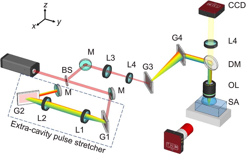
Fig. 1. Schematic of the experimental layout. BS: beam splitter; M: mirror; G1–G4: diffraction gratings; L1–L4: lenses with different focal lengths; DM: dichroic mirror; OL: objective lens; SA: sample. The dashed rectangle indicates the proposed extra-cavity pulse stretcher.
In the SSTF scheme, different frequency components are separated from each other in space by a single-pass grating compressor. It should be noted that the spectral bandwidth of the high-repetition-rate fiber laser system is only ~8 nm, which is smaller than the typical spectral bandwidth of Ti: saphirre chirped pulse amplification system. Such a high-repetition-rate fs laser with a narrow spectral bandwidth needs more angular chirp rate to obtain sufficient spatial dispersion, which also directly introduces a large number of negative Group Delay Dispersion (GDD). However, the large number of negative GDD cannot be compensated by tuning the laser source itself.
To simultaneously obtain sufficient spatial dispersion and compensation for the temporal chirp, we built an extra-cavity pulse stretcher to provide positive temporal chirps, as illustrated in
The GDD introduced by the pulse stretcher can be expressed as
where z is the effective distance of the stretcher,
To obtain a stronger spatiotemporal coupling effect in the SSTF scheme, a telescope system consisting of a convex lens L3 (f = 300 mm) and a concave lens L4 (f = −100 mm) was employed to reduce the beam diameter to ~1 mm (1/e2). The laser beam was then directed through the single-pass grating compressor, which consists of two transmission gratings (G3 and G4, Gitterwerk, 1379 lines/mm, blazing at 1030 nm). The incident angle of the gratings was 45° and the distance between the gratings was ~410 mm. It should be noted that the single-pass grating compressor in the SSTF scheme had two main purposes. On the one hand, the grating compressor introduces proper spatial dispersion, with the grating distance of 410 mm, all the frequency components can fill the pupil of the objective lens. On the other hand, the grating compressor can provide negative GDD, which can be used to compensate for the positive GDD induced by all optics including the pulse stretcher, lenses, and so on. The GDD introduced by the grating compressor in this experiment was estimated to be −4.3756×10⁶ fs2.
After being dispersed by the grating pair, the sizes of the laser beam were measured to be ~13 mm (1/e2) in the chirped dimension and ~1 mm (1/e2) in the non-chirped dimension. The spatially dispersed fs laser pulses were then focused into the glass sample using a water immersion objective lens (Olympus, 20×) with a numerical aperture (NA) of 1.0 and a working distance of 2 mm, the objective lens was immersed in water to minimize spherical aberrations. Notably, the effective NA estimated in this study was only 0.097.
To obtain the shortest pulse duration at the focus of the objective lens in the SSTF scheme, the output pulse from the amplifier should be pre-chirped by adjusting the compressor in the amplifier system. In the experiment, the strongest ionization of the air was observed at the focus of the objective lens when the output pulse duration from the amplifier system was set at –3.5 ps.
The samples used in the experiment were photosensitive glass Foturan (Schott Glass Corp), which were cut into 10 mm × 10 mm × 1.6 mm coupons with all six sides polished. The glass can be regarded as a great indicator for the microfabrication process because the laser-modified area is not visible after the laser irradiation but turns to brown after a thermal annealing process (the temperature was first increased to 500 °C at 5 °C/min and held for one hour; and then raised to 605 °C at 5 °C/min and held for one hour). The glass sample was mounted on a computer-controlled XYZ stage with a resolution of 1 µm, and the front surface of the sample was immersed in purified water. The whole fabrication process was monitored by two charge-coupled devices (CCD) cameras from the top and side, respectively.
3 Theoretical analysis
Theoretically, in the SSTF scheme, the normalized light field of a spatially dispersed pulse E1 at the entrance aperture of an objective lens can be expressed as24, 26, 28.
where E0 is the constant field amplitude, ω0 is the carrier frequency, 2ln2Ω is the FWHM of the frequency spectrum of the pulse, and α(ω−ω0) is the linear shift of each spectral component. In our experiments, the spectral bandwidth was only 8 nm, and the beam waist was ωin = 1 mm. According to ref.18, the angular chirp rate
where d is the distance between the gratings; i and γ are the incident angle and the first-order diffractive angle, respectively; σ is the groove density of the gratings; λ0 is the carrier wavelength. We can calculate the angular chirp rate α = 6.5635 ×10⁻¹⁶ m·s/rad in the experiment. The numerically calculated and experimental measured laser intensity distributions at the entrance aperture of the objective lens are shown in
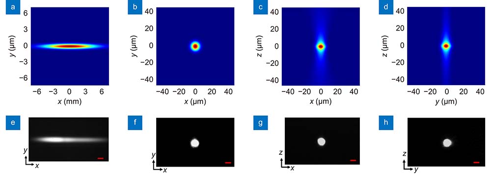
Fig. 2. (a ) Numerically calculated and (e ) experimentally measured laser intensity distributions at the entrance aperture of the objective lens. (b –d ) Numerically calculated and (f –h ) experimentally measured intensity distributions near the focus of the objective lens in XY, XZ-and YZ planes, respectively. Scale bars in (e ) and (f –h ) are 1 mm and 10 µm, respectively.
After passing through the objective lens, the laser field can be calculated using the slowly varying envelope approximation, which can be written as
where k is the wave vector, and f is the focal length of the objective lens. Under the paraxial approximation, the light field near the focus can be described using the Fresnel diffraction formula, which is
By performing an inverse Fourier transform of E3, the intensity distribution in the time domain can be written as
As shown in
4 Results and discussion
3D isotropic fabrication resolution
To verify the 3D symmetrical fabrication using the SSTF scheme, a series of lines in glass samples along different directions were inscribed. The pulse energy, repetition rate, writing speed, and processing depth were set at 8 µJ, 10 kHz, 200 µm/s, and 300 µm beneath the glass surface.
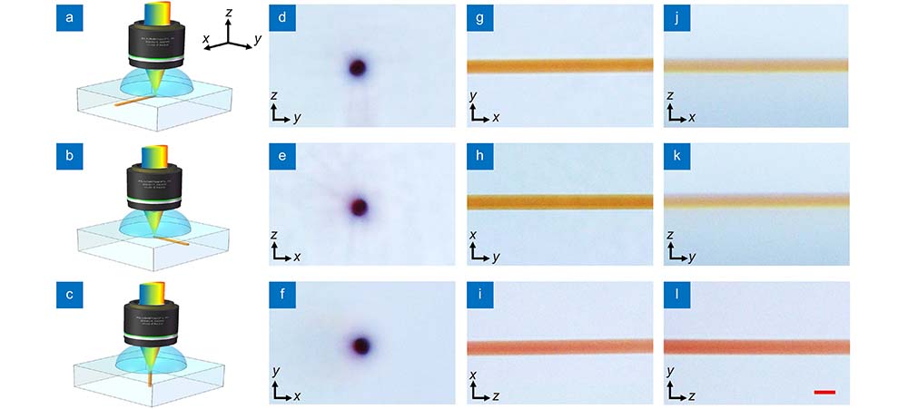
Fig. 3. Schematics of the fabrication procedure with the SSTF scheme along (a ) x, (b ) y, and (c ) z directions, respectively. (d –f ) Cross-sectional, (g –i ) top-view, and (j –l ) side-view optical micrographs of lines along different directions. The pulse energy and writing speed were 8 µJ and 200 µm/s, respectively. Scale bar: 20 µm.
4.2 Influence of pulse energy and writing speed
To further investigate the influence of pulse energy on the fabrication resolution in the SSTF scheme, a series of embedded lines with different pulse energies were written in glass. The writing speed and processing depth were 200 μm/s and 300 µm beneath the surface, respectively. The pulse energies varied from 4.7 μJ to 11.0 μJ.
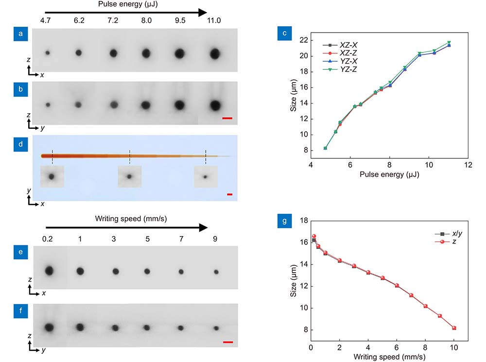
Fig. 4. The influence of pulse energy and writing speed on the fabrication resolution in the SSTF scheme. Cross-sectional optical micrographs of laser-inscribed lines in the glass along (a ) y and (b ) x directions with different pulse energies ranging from 4.7 µJ to 11.0 µJ. (c ) Lateral and longitudinal sizes of lines in XZ and YZ planes versus pulse energies. (d ) A laser-written line using segmented processing with different pulse energies ranging from 11.0 µJ to 4.7 µJ at a writing speed of 5 µm/s. The insets in (d) are the corresponding cross-sectional view optical micrographs. Cross-sectional optical micrographs of several lines inscribed along (e ) y and (f ) x directions at different writing speeds ranging from 0.2 mm/s to 9 mm/s, pulse energy was set at 8 µJ. (g ) Lateral and longitudinal resolutions versus writing speeds. Scale bars indicate 20 µm.
To quantitatively determine the pulse energy dependence of the fabrication resolution, the lateral and longitudinal sizes of cross sections were plotted as functions of pulse energy in
To demonstrate the tunability of fabrication resolution, we fabricated a line using segmented processing with different pulse energies and a writing speed of 5 µm/s (see
To investigate the influence of writing speed on the fabrication resolution, a series of embedded lines at different writing speeds were also inscribed in the glass. The pulse energy and processing depth were set at 8 μJ and 300 µm beneath the surface, respectively. The writing speed varied from 0.2 mm/s to 9 mm/s.
4.3 Influence of processing depth
To investigate the influence of processing depth on the fabrication resolution with the SSTF scheme, a series of lines at different depths and pulse energies were inscribed in glass as illustrated in
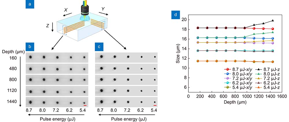
Fig. 5. The influence of processing depth on the fabrication resolution in the SSTF scheme. (a ) Schematic of inscribing lines in glass at different depths along the X and Y directions. Cross-sectional optical micrographs of the lines written along the (b ) X and (c ) Y directions, respectively. (d ) The lateral and longitudinal resolutions versus depth. Scale bar: 20 μm.
4.4 Influence of spherical aberration
To investigate the effect of spherical aberration on the fabrication resolution, we first wrote lines with different pulse energies when the water-immersion objective lens was not immersed in water, as illustrated in
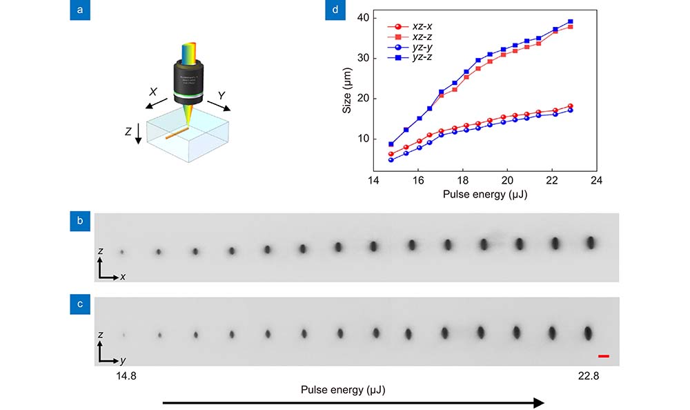
Fig. 6. (a ) Schematic of laser-inscribed lines in the glass when the objective lens was not immersed in water. Cross-sectional optical micrographs of the lines along (b ) Y and (c ) X directions at different pulse energies. The pulse energies varied from 14.8 µJ to 22.8 µJ from left to right in both (b) and (c). (d ) The lateral and longitudinal sizes in XZ and YZ planes versus pulse energies. Scale bar: 20 µm.
As shown in
Moreover, it was found that with a conventional focusing (CF) scheme under the same fabrication parameters, it was impossible to obtain a 3D isotropic resolution (see Fig. S4).
4.5 Demonstration of 3D isotropic fabrication
To demonstrate the unique capability of 3D isotropic fabrication in glass with the SSTF scheme, four helical lines with different pulse energies were inscribed from the rear surface to the front surface of 1.6 mm thick glass.
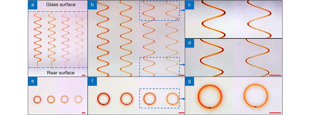
Fig. 7. (a –d ) Cross-sectional view and (e –g ) top-view optical micrographs of helical lines written throughout 1.6 mm thick glass at different pulse energies with the SSTF scheme. The writing speed was set at 200 μm/s, and the pulse energies from left to right were 9.5, 8.0, 7.2, and 6.2 µJ, respectively. (c ) and (d) Enlarged images of (b ) at different depths. (g) Enlarged image in (f ). Scale bar: 100 μm.
3D homogeneous microchannel fabrication
To demonstrate the capability for fabricating spatially homogeneous microfluidic structures, SSTF FLDW-assisted etching was performed as illustrated in
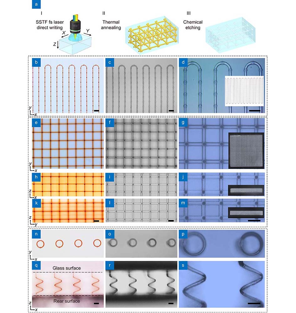
Fig. 8. (a ) Schematic of the fabrication procedure for 3D microchannel structures in glass by a combination of SSTF FLDW assisted etching, which consists of three main steps: (I) SSTF fs laser direct writing; (II) thermal annealing; (III) chemical etching. (b –d ) A meandering cooling structure microchannel. Optical micrographs of the channel structure (b) after FLDW followed by thermal annealing and (c) after etching. (d) An enlarged image in (c). (e –m ) A 3D multilayer microchannel network structure. Optical micrographs of the 3D network structure (e, h, k) after FLDW followed by thermal annealing and after etching in XY, XZ, and YZ planes. (g , j , m ) were enlarged images in (f , i , l ), respectively. (n –s ) 3D helical microchannel structures. The top-view (n ,o ) and side-view (q ,r ) optical micrographs of the 3D helical lines fabricated after FLDW followed by thermal annealing and after etching. (p ) and (s ) are enlarged images in (o) and (r), respectively. The insets in (d, g, j, m) are photographs of the microchannel structures. Scale bar: 100 μm.
To further demonstrate the powerful capability of the fabrication of 3D complicated microfluidic structures by SSTF FLDW assisted etching, a 3D multi-layer microfluidic network structure with a size of 3.75 mm × 3.75 mm × 0.5 mm was fabricated, as shown in the inset of
In addition, four helical hollow microchannels in 500 μm thick glass were also fabricated. The pulse energy and the writing speed were 6.2 μJ and 200 μm/s, respectively.
6 Conclusions
In conclusion, we have successfully applied the SSTF technique to a high-repetition-rate fs fiber laser system and demonstrated the capability of the SSTF technique for 3D isotropic microfabrication with a tunable resolution in the glass. To solve the problem of insufficient pulse compensation for a narrow-bandwidth fiber laser source in the SSTF scheme, we have built a pulse stretcher outside the laser source and confirmed its validity. We have theoretically and experimentally demonstrated that 3D symmetrical intensity distributions near the laser focus can be achieved with the SSTF scheme, respectively. Meanwhile, 3D tunable isotropic fabrication resolution ranging from 8 μm to 22 μm in glass can be achieved by varying the pulse energy of the fs laser, which remains a challenge for the conventional focusing scheme. We also systematically investigated the influences of writing speed, processing depth, and spherical aberration on the fabrication resolution in the SSTF scheme. The cross-sectional size exhibits a nearly linear dependence on the writing speed due to the modulation of exposure doses. The fabrication resolution is insensitive to the depth of the focal position at a certain degree and the rational control of the spherical aberration is of importance for maintaining the 3D isotropic fabrication resolution. This proposed technique overcomes the problem of asymmetric resolution in the conventional FLDW process and extends the processing window of 3D isotropic fabrication resolution, which will be beneficial for developing 3D high-uniform microstructures and novel functional microdevices.
[1] DavisKM, MiuraK, SugimotoN, HiraoK. Writing waveguides in glass with a femtosecond laser. Opt Lett21, 1729–1731 (1996).
[2] MarcinkevičiusA, JuodkazisS, WatanabeM, MiwaM, MatsuoSet al. Femtosecond laser-assisted three-dimensional microfabrication in silica. Opt Lett26, 277–279 (2001).
[3] KawataS, SunHB, TanakaT, TakadaK. Finer features for functional microdevices. Nature412, 697–698 (2001).
[4] ChengY, SugiokaK, MidorikawaK. Microfluidic laser embedded in glass by three-dimensional femtosecond laser microprocessing. Opt Lett29, 2007–2009 (2004).
[5] KowaleviczAM, SharmaV, IppenEP, FujimotoJG, MinoshimaK. Three-dimensional photonic devices fabricated in glass by use of a femtosecond laser oscillator. Opt Lett30, 1060–1062 (2005).
[6] SugiokaK, ChengY, MidorikawaK. Three-dimensional micromachining of glass using femtosecond laser for lab-on-a-chip device manufacture. Appl Phys A81, 1–10 (2005).
[7] SugiokaK, ChengY. Ultrafast lasers—reliable tools for advanced materials processing. Light Sci Appl3, e149 (2014).
[8] MalinauskasM, ŽukauskasA, HasegawaS, HayasakiY, MizeikisVet al. Ultrafast laser processing of materials: from science to industry. Light Sci Appl5, e16133 (2016).
[9] XuJ, LiXL, ZhongY, QiJ, WangZHet al. Glass-channel molding assisted 3D printing of metallic microstructures enabled by femtosecond laser internal processing and microfluidic electroless plating. Adv Mater Technol3, 1800372 (2018).
[10] LinZJ, XuJ, SongYP, LiXL, WangPet al. Freeform microfluidic networks encapsulated in laser‐printed 3D macroscale glass objects. Adv Mater Technol5, 1900989 (2020).
[11] LiuZM, XuJ, LinZJ, QiJ, LiXLet al. Fabrication of single-mode circular optofluidic waveguides in fused silica using femtosecond laser microfabrication. Opt Laser Technol141, 107118 (2021).
[12] JiaYC, WangSX, ChenF. Femtosecond laser direct writing of flexibly configured waveguide geometries in optical crystals: fabrication and application. Opto-Electron Adv3, 190042 (2020).
[13] TanDZ, WangZ, XuBB, QiuJR. Photonic circuits written by femtosecond laser in glass: improved fabrication and recent progress in photonic devices. Adv Photon3, 024002 (2021).
[14] WolfA, DostovalovA, BronnikovK, SkvortsovM, WabnitzSet al. Advances in femtosecond laser direct writing of fiber Bragg gratings in multicore fibers: technology, sensor and laser applications. Opto-Electron Adv5, 210055 (2022).
[15] SugiokaK, XuJ, WuD, HanadaY, WangZKet al. Femtosecond laser 3D micromachining: a powerful tool for the fabrication of microfluidic, optofluidic, and electrofluidic devices based on glass. Lab Chip14, 3447–3458 (2014).
[16] SerienD, SugiokaK. Fabrication of three-dimensional proteinaceous micro- and nano-structures by femtosecond laser cross-linking. Opto-Electron Adv1, 180008 (2018).
[17] ChengY, SugiokaK, MidorikawaK, MasudaM, ToyodaKet al. Control of the cross-sectional shape of a hollow microchannel embedded in photostructurable glass by use of a femtosecond laser. Opt Lett28, 55–57 (2003).
[18] AmsM, MarshallGD, SpenceDJ, WithfordMJ. Slit beam shaping method for femtosecond laser direct-write fabrication of symmetric waveguides in bulk glasses. Opt Express13, 5676–5681 (2005).
[19] OsellameR, TaccheoS, MarangoniM, RamponiR, LaportaPet al. Femtosecond writing of active optical waveguides with astigmatically shaped beams. J Opt Soc Am B20, 1559–1567 (2003).
[20] SugiokaK, ChengY, MidorikawaK, TakaseF, TakaiH. Femtosecond laser microprocessing with three-dimensionally isotropic spatial resolution using crossed-beam irradiation. Opt Lett31, 208–210 (2006).
[21] VishnubhatlaKC, BelliniN, RamponiR, CerulloG, OsellameR. Shape control of microchannels fabricated in fused silica by femtosecond laser irradiation and chemical etching. Opt Express17, 8685–8695 (2009).
[22] ZhuGH, vanHowe J, DurstM, ZipfelW, XuC. Simultaneous spatial and temporal focusing of femtosecond pulses. Opt Express13, 2153–2159 (2005).
[23] OronD, TalE, SilberbergY. Scanningless depth-resolved microscopy. Opt Express13, 1468–1476 (2005).
[24] HeF, XuH, ChengY, NiJL, XiongHet al. Fabrication of microfluidic channels with a circular cross section using spatiotemporally focused femtosecond laser pulses. Opt Lett35, 1106–1108 (2010).
[25] VitekDN, AdamsDE, JohnsonA, TsaiPS, BackusSet al. Temporally focused femtosecond laser pulses for low numerical aperture micromachining through optically transparent materials. Opt Express18, 18086–18094 (2010).
[26] HeF, ChengY, LinJT, NiJL, XuZZet al. Independent control of aspect ratios in the axial and lateral cross sections of a focal spot for three-dimensional femtosecond laser micromachining. New J Phys13, 083014 (2011).
[27] KammelR, AckermannR, ThomasJ, GötteJ, SkupinSet al. Enhancing precision in fs-laser material processing by simultaneous spatial and temporal focusing. Light Sci Appl3, e169 (2014).
[28] ZengB, ChuW, GaoH, LiuWW, LiGHet al. Enhancement of peak intensity in a filament core with spatiotemporally focused femtosecond laser pulses. Phys Rev A84, 063819 (2011).
[29] HeF, ZengB, ChuW, NiJL, SugiokaKet al. Characterization and control of peak intensity distribution at the focus of a spatiotemporally focused femtosecond laser beam. Opt Express22, 9734–9748 (2014).
[30] TanYX, WangZH, ChuW, LiaoY, QiaoLLet al. High-throughput in-volume processing in glass with isotropic spatial resolutions in three dimensions. Opt Mater Express6, 3787–3793 (2016).
[31] TanYX, ChuW, WangP, LiWB, QiJet al. High-throughput multi-resolution three dimensional laser printing. Phys Scr94, 015501 (2019).
[32] SunBS, SalterPS, RoiderC, JesacherA, StraussJet al. Four-dimensional light shaping: manipulating ultrafast spatiotemporal foci in space and time. Light Sci Appl7, 17117 (2018).
[33] QuinomanP, ChimierB, DuchateauG. Theoretical study of spatiotemporal focusing for in-bulk laser structuring of dielectrics. J Opt Soc Am B39, 166–176 (2022).
[34] ChengWB, WangZH, LiuXL, ChengY, PolynkinP. Microexplosions in bulk sapphire driven by simultaneously spatially and temporally focused femtosecond laser beams. Opt Lett48, 751–754 (2023).
[35] HansenWW, JansonSW, HelvajianH. Direct-write UV-laser microfabrication of 3D structures in lithium-aluminosilicate glass. Proc SPIE2991, 104–112 (1997).
[36] ChengY, SugiokaK, MasudaM, ShihoyamaK, ToyodaKet al. Optical gratings embedded in photosensitive glass by photochemical reaction using a femtosecond laser. Opt Express11, 1809–1816 (2003).
[37] MartinezO. 3000 times grating compressor with positive group velocity dispersion: application to fiber compensation in 1.3-1.6 µm region. IEEE J Quantum Electron23, 59–64 (1987).
[38] YuJP, XuJ, DongQN, QiJ, ChenJFet al. Low-loss optofluidic waveguides in fused silica enabled by spatially shaped femtosecond laser assisted etching combined with carbon dioxide laser irradiation. Opt Laser Technol158, 108889 (2023).
Article Outline
Yuanxin Tan, Haotian Lv, Jian Xu, Aodong Zhang, Yunpeng Song, Jianping Yu, Wei Chen, Yuexin Wan, Zhaoxiang Liu, Zhaohui Liu, Jia Qi, Yangjian Cai, Ya Cheng. Three-dimensional isotropic microfabrication in glass using spatiotemporal focusing of high-repetition-rate femtosecond laser pulses[J]. Opto-Electronic Advances, 2023, 6(10): 230066.
