红外与激光工程, 2023, 52 (9): 20230450, 网络出版: 2023-10-23  

星敏感器遮光罩检测技术研究(特邀)

Research on baffle detection technology for star sensor (invited)
作者单位
上海航天控制技术研究所,上海 201109
摘要
星敏感器在轨工作期间周期性地受到以太阳光为主要来源的杂散光干扰,导致恒星或感知目标捕获失效,轻者姿态数据无效,重者面临被非合作目标定向攻击。在杂散光抑制过程中,遮光罩可将太阳光消减至10−5~10−6量级,从而有效减少太阳光对像面的污染。然而,在遮光罩研制过程中,因散射模型精度不高、挡光环刃口厚度无法有效测量,导致实际遮光罩消光性能达不到预期设计要求。文中在粗糙度为1.0 μm铝合金基材上测量Magic black消光涂层,并拟合出偏差小于10%的散射模型;针对挡光环刃口的特殊构造,提出利用同轴远心光路检测刃口厚度,检测精度优于1.2 μm;最后以遮光罩消光比定量测试以及外场杂散光观星测试考核遮光罩杂散光抑制性能。结果表明,用拟合后的BRDF散射模型,比朗伯散射体精度提升40%;刃口检测可保障遮光罩消光性能,使得遮光罩消光比理论仿真与实际测试偏差小于12%;暗室杂散光测试使得在24°太阳光入射时像面平均灰度为55.80;外场观星杂散光测试时精度变化量不超过0.5″。该星敏感器遮光罩检测方法可为其他光电类敏感器提供理论基础与技术支持。
Abstract
ObjectiveStar sensor are mainly used to achieve star attitude and perceive non-cooperative targets. When the equivalent magnitude of a constant star or non-cooperative target is large, the detection and capture of stars or sensing targets will cease to be effective due to the influence of stray light. Therefore, the suppression performance of stray light is a key technical indicator of situational awareness sensors. Engineering experience has shown that a first-order sunshade can reduce sunlight to 10-5-10-6, effectively reducing sunlight pollution on the detector image surface and improving the probability of target capture. In the design stage of the baffle, the scattering characteristics of the extinction coating on the inner surface of the baffle are often modeled as Lambert bodies, resulting in significant differences between the actual and expected values of the extinction performance; During the processing stage of the light retaining ring, the thickness of the cutting edge is often ignored, resulting in significant differences between the actual and expected values of the extinction performance of the light retaining ring. MethodsTo solve the technical problem of projects mentioned above, this article conducts theoretical and engineering research from two technical approaches of measurement and modeling of BRDF, and cutting edge thickness measurement. Firstly, based on the commonly used fitting formula of BRDF, the visualized model for the scattering characteristics of Magic black extinction coating on the aluminum alloy base of 1.0 μm thickness is built. The blue box represents the measurement data and the white box represents the fitting data (Fig.4). The figures demonstrate the scattering characteristics of the coating surface BRDF values changing with different incident zenith angles and reflected zenith angles when the detection azimuth angle is 180° and the incident light wavelengths are 500 nm, 550 nm, 600 nm, 650 nm, and 700 nm, respectively; Secondly, edge thickness detection is carried out (Fig.5). Considering the particularity of the position of the edge structure, this paper proposes a dual telecentric coaxial light illumination scheme for edge thickness detection. The detection optical path is shown (Fig.6). The basic principle is that the collimated light source is incident onto the right side optical path through a semi-transparent and semi-reflective mirror, and is reflected onto the edge of the light blocking ring through a reflector. Due to the use of a coaxial telecentric optical path, the edge imaging is clear and sharp. The beam scatters return to the optical path through the edge. After passing through a semi-transparent and semi-reflective mirror, the imaging side's telecentric optical path is incident onto the detector's image plane. As shown in Fig.9, calibration with the imaging instrument, the measurement accuracy is better than 1.2 μm. The measurement data of the cutting edge is shown (Fig.12), 30 points are collected from each light blocking ring cutting edge, evenly divided into one circle. The figures show that the thickness of the cutting edge at each point is different, while the thickness variation range is controlled within 20-27 μm.Results and DiscussionsIn the article, quantitative testing of the extinction ratio of the light shield and outdoor stray light observation testing are used to evaluate the stray light suppression performance of the baffle. The quantitative testing plan and equipment used for extinction ratio are shown (Fig.13, Tab.2), and the test data is shown (Fig.15). The three extinction ratio curves represent the theoretical values, measured values, and Lambert scattering model values after using the BRDF model. The starting angle of the test is 24° and the ending angle is 72°. From the graph, it can be seen that within the range of 24° to 60°, the test value is close to the theoretical value, with a deviation of about 12%, and the data trend is consistent; The dark room stray light test (photoelectric whole machine test) is shown (Fig.16), and the test data is shown (Fig.17). When the sunlight and the optical axis of the situation sensing sensor are incident at 24°, the average gray level of the image plane is 55.80, the maximum gray level is 134, the RMS is 10.73°, and the entropy is 6.18. As the testing angle gradually increases, the average gray level is 51.35 at 12°; The field stray light star observation test site is shown (Fig.18), and the experimental data is shown (Fig.19). Under stray light irradiation conditions, the background gray level of the image increases, and the signal-to-noise ratio between the original star target and the deep space background decreases. The stray light contaminated area may produce false star point targets or equivalent dark current noise or detector electronic noise, resulting in errors in attitude recognition process.ConclusionsThis article demonstrates the detection result of key components of the baffle in the process of suppressing stray light for situational awareness sensors from two different stages of design and processing. The design stage mainly tests the bidirectional reflection distribution function based on the scattering characteristics of the Magic black extinction coating on the process components, and fits visual data suitable for optical simulation analysis; In the processing stage, based on the key characteristics of the cutting edge, a coaxial dual telecentric optical path is proposed to detect its thickness, a testing platform was built, and the measured data of the cutting edge were obtained; In the verification section of the article, quantitative testing of the extinction ratio of the baffle was carried out, and its extinction performance was further verified by testing the stray light of the entire machine. The data shows that the deviation between the quantitative test value and the theoretical simulation value of the extinction ratio was 12%, and the average gray level of the image caused by sunlight incident at 24° on the hood was 55.80; The accuracy of star point positioning is changed from 2.5″ (3σ) without stray light pollution to 3.0" (3σ). This article provides a theoretical basis and technical support for the detection method of the situation perception sensor cover for other optoelectronic sensors.

0 引 言

新一代星敏感器既可以实现恒星姿态捕获,又可以感知非合作目标。当非合作目标距离本体较远时,可将目标近似等效5700 K色温恒星,该恒星星等随与本体距离远近而发生变化。当恒星星等或非合作目标等效星等较大时,受杂散光的影响导致恒星或感知目标探测捕获失效,因此杂散光的抑制性能是星敏感器的关键技术指标,工程经验表明,一阶遮光罩可将太阳光消减至10−5~10−6,从而有效减少太阳光对探测器像面的光污染,提高目标被捕获的概率。

在遮光罩设计阶段,常常将表面涂层的散射特性等效为朗伯体,或者将仿真软件自带的散射特性附着在表面属性里,因此设计出来的遮光罩消光性能与预期值存在较大的差异。双向反射分布函数(BRDF)最早是由美国学者Nicodemus提出的,它表征了在不同入射角条件下物体表面任意观测角的反射特性。2016年,中国科学院西安光学精密机械研究所对铝板样品表面喷涂了Z306消光黑漆,并进行了双向反射分布函数测量与建模,获得了Z306铝板样片在650 nm波段处的BRDF值[1];2019年,长春理工大学搭建了一种用于测试有机玻璃(PMMA) BRDF的测试设备,并获得该有机玻璃的BRDF[2];2022年,沈阳工业大学提出了一种改进多参量微面元偏振的BRDF模型,并基于斯托克斯矢量与穆勒矩阵的关系建立反射光偏振度数学模型[3]。上述文献虽然对样品进行测试、优化模型,但是所用样品吸收率不高(约为95%),缺少对高吸收率涂层BRDF的检测与建模。

在遮光罩加工阶段,需要对挡光环的刃口进行精密加工,确保刃口厚度满足指标要求。2019年,中国科学院西安光学精密机械研究所对超轻型光机系统结构杂光抑制技术进行了研究,通过对挡光环及刃口的优化设计,将黑色涂层处理后的挡光环刃口厚度由原来一体化加工时的0.20 mm减小到0.03 mm,降低了所有挡光环刃口的累积反射面积[4-7];2022年,上海航天控制技术研究所将遮光罩刃口厚度进一步优化设计,分析了对于不同消光性能所需要的刃口厚度[8]。上述研究虽然论证了刃口厚度对杂散光的影响,但是没有给出刃口厚度检测方案。

基于上述检测过程中存在的不足,文中在粗糙度为1.0 μm铝合金基材上测量Magic black消光涂层,并拟合出偏差小于10%的散射模型,该模型与传统朗伯模型相比仿真精度提升了40%;其次,对遮光罩挡光环刃口厚度检测方法进行研究,提出基于同轴远心光路检测刃口厚度检测的方法,在不破坏遮光罩(或挡光环,前者特指遮光罩与挡光环一体加工,后者特指遮光罩与挡光环分体加工)的前提下实现对刃口厚度的精密测量,测量精度优于1.2 μm;最后,开展了遮光罩消光比定量测试、暗室杂散光测试以及外场杂散光观星测试,消光比测试数据表明,遮光罩理论消光比与实际偏差为12%,暗室测试数据表明,在24°太阳光入射时像面平均灰度为55.80,外场测试数据表明,当有杂散光干扰时测量精度变化量不超过0.5″。

1 遮光罩检测技术特点

1.1 BRDF测量与数据拟合

BRDF定义如公式(1)所示,对于给定波长指定方向上的辐亮度除以给定方向上的辐照度,如图1所示。

$ {f_{{\text{BRDF}}}}({\theta _i},{\varPhi _i},{\theta _r},{\varPhi _r}) = \frac{{{\rm{d}}{L_r}({\theta _i},{\varPhi _i},{\theta _r},{\varPhi _r})}}{{{\text{d}}{E_i}({\theta _i},{\varPhi _i})}} $ (1)

式中: ${f}_{{\text{BRDF}}}$为双向反射分布函数; $ {\theta _i} $为入射天顶角; $ {\varPhi _i} $为入射方位角; $ {E_i} $为入射光辐照度; $ {\theta _r} $为反射天顶角; $ {\varPhi _r} $为反射方位角; $ {L_r} $为反射光辐亮度。

图 1. BRDF测量

Fig. 1. BRDF measurement

下载图片 查看所有图片

目前,国际上通用的具有航天飞行经验的高吸收率消光涂层为Magic black,相比于PNC涂层,Magic black由于涂覆工艺采用真空沉积技术,涂层厚度为3~5 μm,均匀性良好,样品如图2所示。

由于星敏感器遮光罩对刃口厚度具有严格的控制要求,选用Magic black涂层比较合适。文中选用标准的BRDF检测设备对粗糙度为1.0 μm样品进行检测,如图3所示。测试数据用公式(2)进行拟合。

图 2. Magic black消光涂层

Fig. 2. Magic black matting coating

下载图片 查看所有图片

图 3. BRDF检测系统

Fig. 3. Detection system of BRDF

下载图片 查看所有图片

$ \left\{ {\begin{array}{*{20}{c}} {{f_{{\rm{BRDF}}}} = \dfrac{{{k_s} \cdot \ln (1 + \cos {\theta _i} \cdot \cos {\theta _r}) \cdot a \cdot b + c}}{{\cos {\theta _i} \cdot \cos {\theta _r}}}}\\ {a = \dfrac{{{k_r}}}{{1 + (k_r^2 - 1) \cdot \cos \alpha }} \cdot \dfrac{{{\sigma ^2}}}{{2\pi }} \cdot \dfrac{{{p_1}\lambda + {p_2}}}{{{\lambda ^2} + {q_1}\lambda + {q_2}}}}\\ {b = \exp ( - {\sigma ^2} \cdot {{\tan }^2}(\alpha ) \cdot {{(2{\lambda ^2} \cdot K)}^{ - 1}})}\\ {c = \dfrac{{{k_d}}}{\pi }}\\ {\cos \alpha = \dfrac{{\cos {\theta _i} + \cos {\theta _r}}}{{2\cos \gamma }}}\\ {\cos \gamma = \sqrt {(\cos {\theta _i} \cdot \cos {\theta _r} + \sin {\theta _i} \cdot \sin {\theta _r} \cdot \cos \varphi + 1)/2} } \end{array}} \right. $ (2)

式中: $ {\theta _i} $为入射天顶角; $ {\theta _r} $为反射天顶角; $ \lambda $为光波波长; $ \sigma $为材质表面粗糙度; $ \varphi $为方位角; ${k_{{s}}}$${k_{{r}}}$${k_{{d}}}$$ K $$ {p_1} $$ {p_2} $$ {q_1} $$ {q_2} $为待定系数。对于粗糙度为1.0 μm的建模可视图如图4所示,蓝框为测量数据,白框为拟合数据,其物理意义如下:当探测方位角为180°且确定某一测量波长后,BRDF数值随不同入射天顶角和反射天顶角变化。

图 4. BRDF拟合数据

Fig. 4. Fitting data of BRDF

下载图片 查看所有图片

拟合数据与测量数据偏差优于10%,将拟合数据代入杂散光仿真软件,可进行光束追迹。

1.2 刃口测量

刃口属于遮光罩关键部组件,图5所示为一直角挡光环,刃口位于挡光环内径边缘,由于所处的结构位置特殊,并且厚度尺寸过小,导致一般的检测设备如三坐标、影像仪无法对其直接进行测量。刃口厚度在业内还没有标准的测量规范,传统做法是将加工好的挡光环剖开,用影像仪或者万能工具显微镜检测刃口厚度。这种检测方案的前提是要求精加工批量一致性良好,同时要求剖开后的挡光环刃口不变形。然而,在实际加工过程中,刀口切削金属时会有损坏,导致刃口一致性并不理想,所以这种破坏式的检测并不符合实际工程需求。

图 5. 刃口示意图

Fig. 5. Schematic diagram of the edge

下载图片 查看所有图片

文中采用双远心同轴光照明检测刃口厚度,检测光路如图6所示,准直光源经过半透半反镜入射到右侧光路,经过反射镜反射至挡光环刃口处,由于采用同轴远心光路,刃口图像清晰锐利,光束经过刃口散射返回光路,再经过半透半反镜后,形成了像方远心的光路,随后入射到探测器像面。

图 6. 双远心同轴光检测挡光环刃口

Fig. 6. Dual telecentric coaxial optical detection of light-blocking ring edges

下载图片 查看所有图片

双远心光学系统畸变与传递函数如图7所示,全视场畸变量小于0.05%,传递函数为210 lp/mm≥0.62(配套探测器像元尺寸为2.4 μm)。

为解决刃口自身的偏差造成图像上的差异,采用动态阈值分割法和NCC模板匹配算法相结合对目标进行搜索。具体流程如图8所示。

图 7. 像质分析。(a)畸变;(b) MTF

Fig. 7. Analysis of image quality. (a) Distortion; (b) MTF

下载图片 查看所有图片

图 8. 基于灰度图像的刃口识别与刃口厚度计算算法流程示意图

Fig. 8. Flow diagram of the algorithm for edge recognition and edge thickness calculation based on grayscale image

下载图片 查看所有图片

动态阈值分割方法是将图像与其局部背景进行比较的操作。设 ${f_{r,c}}$表示输入的灰度图像, ${g_{r,c}}$表示平滑后, ${g_{diff}}$表示设定的阈值。动态阈值分割处理中,计算平滑图像时所采用的平滑滤波器的尺寸决定了能被分割出来的物体尺寸。

当提取的目标物体的亮度高于局部背景时,动态阈值分割得到的区域为:

$ S = \{ {(r,c)^{\rm{T}}} \in R|{f_{r,c}} - {g_{r,c}} \geqslant {g_{diff}}\} $ (3)

当提取的目标物体的亮度低于局部背景时,动态阈值分割得到的区域为:

$ S = \{ {(r,c)^{\rm{T}}} \in R|{f_{r,c}} - {g_{r,c}} \leqslant {{ - }}{g_{diff}}\} $ (4)

当提取的目标物体的亮度不均匀时,动态阈值分割得到的区域为:

$ S = \{ {(r,c)^{\rm{T}}} \in R|\left| {{f_{r,c}} - {g_{r,c}}} \right| \geqslant {g_{diff}}\} $ (5)

NCC (Normalized Cross Correlation)算法即归一化积相关算法,利用子图与模板图的灰度,通过归一化的相关性度量公式来计算二者之间的匹配程度。

$ R\left( {i,j} \right) = \dfrac{{\displaystyle\sum\nolimits_{S = 1}^M {\displaystyle\sum\nolimits_{t = 1}^N {\left| {{S^{i,j}}(s,t) - E({S^{i,j}})} \right| \cdot \left| {T(s,t - E(T))} \right|} } }}{{\sqrt {\displaystyle\sum\nolimits_{S = 1}^M {\displaystyle\sum\nolimits_{t = 1}^N {{{\left[ {{S^{i,j}}(s,t) - E({S^{i,j}})} \right]}^2} \cdot \displaystyle\sum\nolimits_{S = 1}^M {\displaystyle\sum\nolimits_{t = 1}^N {{{\left[ {T(s,t - E(T))} \right]}^2}} } } } } }} $ (6)

式中: $ E({S^{i,j}}) $$ E(T) $分别表示(i, j)处子图、模板的平均灰度值。通过上述算法完成提取刃口的轮廓直线,获得上下刃口直线的方程:

$ \left\{ {\begin{array}{*{20}{c}} {{a_1}x + {b_1}y + {c_1} = 0} \\ {{a_2}x + {b_2}y + {c_2} = 0} \end{array}} \right. $ (7)

式中: $ {a_1} $$ {a_2} $$ {b_1} $$ {b_2} $$ {c_1} $$ {c_2} $均为直线方程的参数。利用该方程计算直线间距离,获得刃口在图像平面上的尺寸,代入公式(8)求解刃口厚度。

$ \begin{split} \\ a = \beta \cdot {s_e} \end{split} $ (8)

式中:a为图像上刃口尺寸;β为镜头放大率; $ {s_e} $为刃口厚度。选取探测器像素尺寸为2.4 μm,远心镜头放大倍率为3倍,则在不考虑细分精度的前提下,系统测量精度为0.8 μm。现将双远心测试系统向测量精度为1.2 μm的影像仪标校,如图9所示,图9(a)为对标靶板,图9(b)为两个测量系统数值偏差。

图 9. 测试系统数据标校。(a)分划板;(b)测量精度

Fig. 9. Test system data calibration. (a) Reticle; (b) Measurement accuracy

下载图片 查看所有图片

刃口检测平台搭建如图10所示,设备构成如表1所示,包括高精度双远心同轴光路物镜、多功能探针、一维气浮转台。检测前,第一步需要通过多功能探针采样,将挡光环中心轴线与转台一致;第二步用双远心同轴光路镜头对刃口清晰成像;第三步启动气浮转台,对刃口数据进行采集。

图 10. 刃口检测示意图

Fig. 10. Schematic of edge inspection

下载图片 查看所有图片

表 1. 试验条件技术表

Table 1. Table of experimental conditions and techniques

Serial numberTitleTechnical requirement
1Magnification
2Light sourceLED
3NA0.1
4Position accuracy/(″)1.0
5Face runout/μm1.0
6Multi-function probes/μm1.0

查看所有表

刃口影像如图11所示,由于受限于光学系统的景深,仅可对刃口区域清晰成像,图中红色框线内的白色线条即为刃口影像。影像测量的优势是可以实现在不破坏挡光环的前提下实现非接触测量,优点是高效、直观、测量精度高。在工程应用上存在两个缺点:1) 由于光学系统需要配备同轴光源,导致光学系统体积较大,对待检测的挡光环内径尺寸受限;2) 挡光环表面附着超高吸收涂层后,会影响图像质量,通常需要在表面处理之前进行刃口数据采集。由于文中使用的是Magic black消光涂层,其特点是厚度仅为3~5 μm,相对刃口厚度可以忽略不计,因此检测表面处理前的刃口就可以满足需求。

图 11. 影像法测量遮光罩刃口

Fig. 11. Measurement of mask edge by imaging method

下载图片 查看所有图片

刃口测量数据如图12所示,每个挡光环刃口采集30个点,均分一圈,可以看出,每个点刃口厚度均不相同,但厚度变化范围都控制在20~27 μm以内。

图 12. 挡光环刃口厚度测试数据

Fig. 12. Light-blocking ring edge thickness test data

下载图片 查看所有图片

2 杂散光试验验证

2.1 消光比测试

消光比检测原理如图13所示[9-19],由多维控制转台、太阳模拟器、暗室、光学平台、消光陷阱、复合辐照度计、数据采集系统构成,其性能指标如表2所示。

图 13. 遮光罩消光比测试原理图

Fig. 13. Schematic diagram of mask extinction ratio test

下载图片 查看所有图片

表 2. 试验条件和技术

Table 2. Table of experimental conditions and techniques

Serial numberTitleTechnical requirement
1Cleanliness10000 level
2Illumination of darkroomless than seventh-magnitude stars’ level
3Standard of solar simulatorAAA
4Output of solar constant/lx130000
5Positioning accuracy of rotary table/(″)20
6Dynamic range160 dB (Composite irradiometer)
7Angle measuring range/(°)24-72

查看所有表

第一步用积分球测量太阳模拟器辐照度,作为测试基准;第二步将遮光罩安装在多维控制转台上,校准遮光罩与太阳模拟器光轴;第三步将复合辐照度计调节至遮光罩有效出瞳口径,并微调前后位置,使开口位于在光学理论位置上;第四步调整多维控制转台,使太阳模拟器与遮光罩成 $ \theta $起始测试角度;第五步以2°为步长,采集数据。消光比定义如公式(9)所示:

$ {E_R}\left( \theta \right) = \frac{{{E_{\text{o}}}\left( \theta \right){D^2}_{\rm{o}}}}{{{E_i}{D^2}_i\cos \theta }} $ (9)

式中: $ {E_R} $为消光比; $ {E_{\text{o}}} $为遮光罩出口辐照度; $ {E_i} $为太阳光正入射遮光罩入口处辐照度; ${D_{\rm{o}}}$为遮光罩有效出瞳口径; $ {D_i} $为遮光罩有效入瞳口径; $ \theta $为太阳光与遮光罩光轴夹角。遮光罩光学参数如图14所示,刃口厚度设计值为30.0 μm,遮光罩长度为166.2 mm,有效通光口径为96.6 mm,有效出光口径为40.0 mm。挡光环为扁平环状结构,其轴向刚度较低,而刃口又处于结构的最薄弱位置,因此需尽可能减小其切削力,同时每次加工前需充分时效。对于环状结构,车削是理想的加工方式。其主要加工参数如下:切削速度V=400 m/min;切深ap=0.005 mm;进给量f=0.010 mm/rev,该加工参数能够减小加工后的残余应力。

图 14. 遮光罩设计参数

Fig. 14. Baffle design parameters

下载图片 查看所有图片

测试数据如图15所示,三条消光比曲线分别代表使用BRDF模型后的理论值、实测值、朗伯散射模型值。测试起始角度为24°,终止角度为72°,可以看出,在24°~60°区间内,测试值与理论值接近,偏差约为12%,数据趋势一致;理论值与朗伯值偏差约为40%;在60°~72°区间内,测试值与理论值偏差逐渐增大,并且数据趋势发生改变,这是由于在弱光检测过程中,随着入射到复合辐照度计里的光越来越弱,环境引起的干扰误差越来越强,在该测试中,当离轴角度达到60°后,环境光成为主干扰项,因此会对测试结果产生一定偏离。

图 15. 消光比检测

Fig. 15. Extinction ratio detection

下载图片 查看所有图片

2.2 暗室杂散光测试

试验技术条件与表2一致,更换遮光罩出口处转接工装,将待测试的星敏感器安装在多维控制转台上,并与太阳模拟器光轴成24°夹角,试验现场如图16所示。在测试过程中需要控制关键散射面,比如光学平台表面覆盖消光材料,尽可能减少环境散射光对测试结果的影响。

图 16. 暗室杂散光测试图

Fig. 16. Stray light test in darkroom

下载图片 查看所有图片

试验数据如图17所示,当太阳光与星敏感器光轴成24°入射时,像面平均灰度为55.80,最大灰度为134,RMS为10.73,熵为6.18。根据图像算法,当灰度值不饱和时,可以提取相关信息,即在该测试条件下,最大像面灰度约为总灰度值的52%,具备暗弱目标被提取的必要条件。随着测试角度逐渐增大,平均灰度在26°时为51.35;在28°时为47.20;在30°时为45.44。

图 17. 杂散光测试数据

Fig. 17. Stray light test data

下载图片 查看所有图片

2.3 外场试验

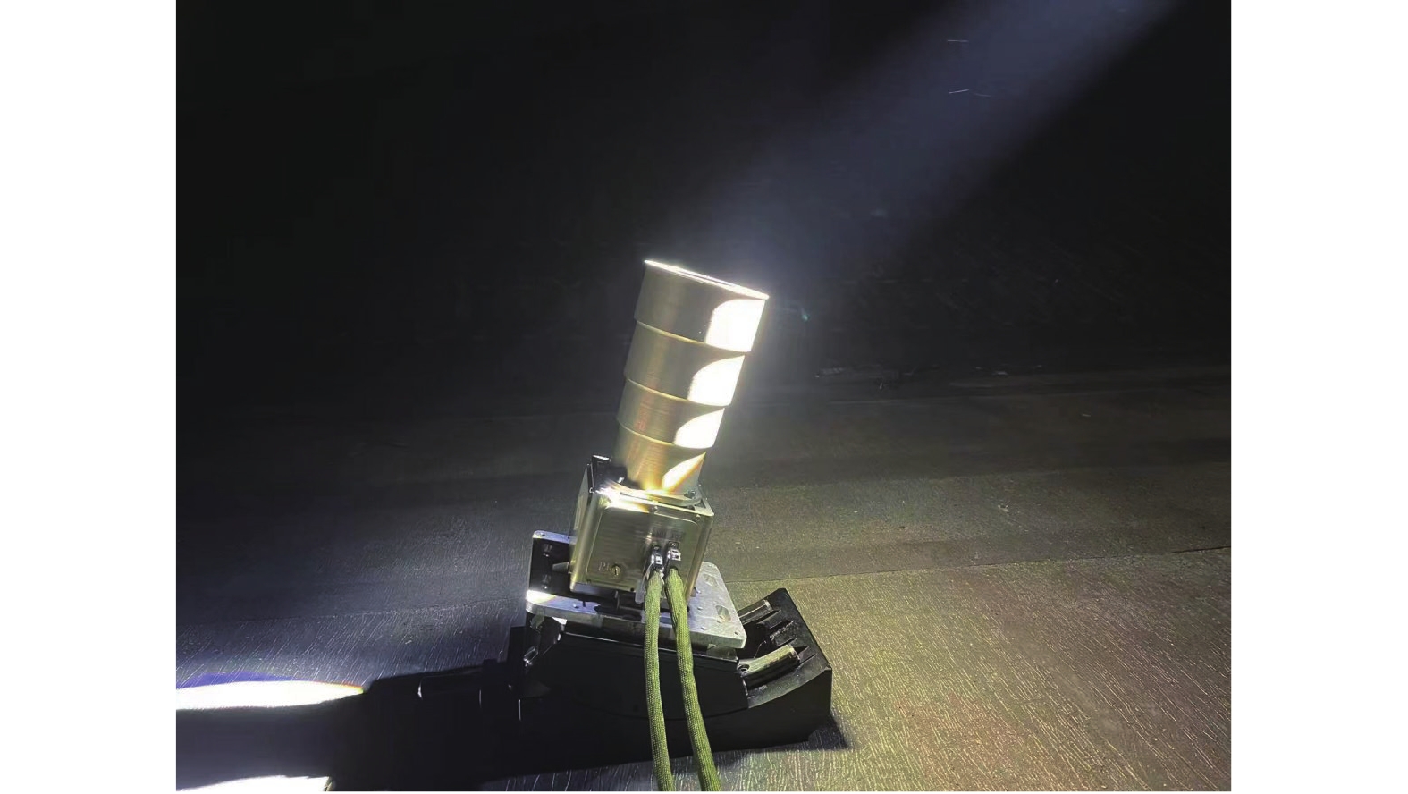
外场试验试验条件为一个太阳常数平行光与星敏感器成24°夹角入射。对比试验条件分为无光入射和使用文中提及的遮光罩在相同试验状态下的测试。试验现场如图18所示,试验数据如图19所示,在杂散光照射条件下,图像的背景灰度上升,原本的恒星目标能量与深空背景之间的信噪比下降,杂散光污染区域可能产生假星点目标或者等效成暗电流噪声或探测器电子学噪声,从而在姿态识别过程中产生误差。图19(a)为在外场无杂光污染环境下观星的精度,蓝色表示x方向的误差,红色表示y方向的误差。在正常环境下观星的误差小于2.5″(3σ);图19(b)为在外场有杂光污染环境下观星的精度,星敏感器在有杂散光污染环境下观星的误差小于3.0″(3σ)。
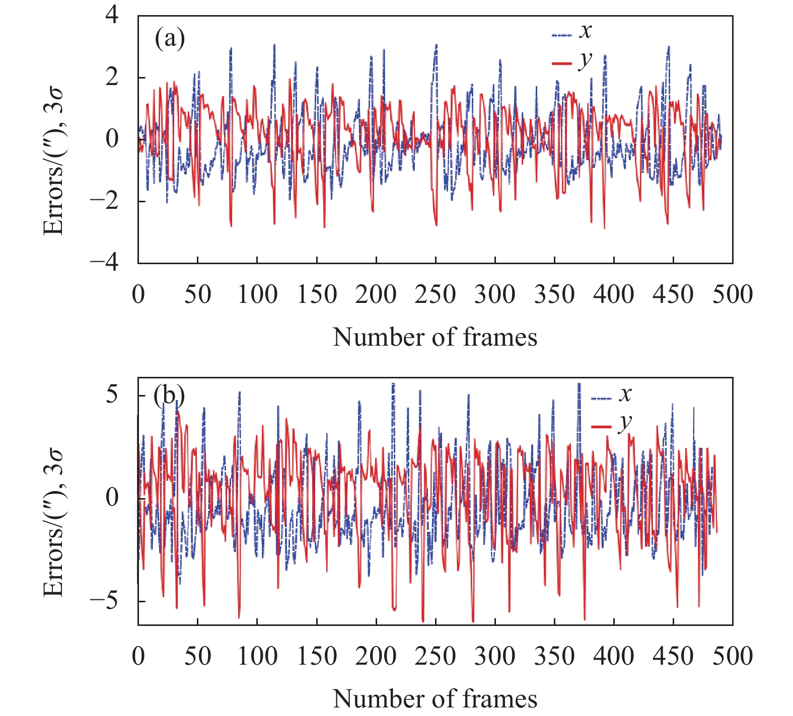
图 18. 外场杂散光测试图

Fig. 18. Stray light test at outfield

下载图片 查看所有图片

图 19. 观星测试数据。(a)无杂散光干扰;(b)有杂散光干扰时测角精度

Fig. 19. Stargazing test data. (a) Accuracy of star sensor without stray light; (b) Accuracy of star sensor interfered by stray light using the baffle mentioned in this paper

下载图片 查看所有图片

3 结 论

文中基于设计、加工两个不同阶段对星敏感器遮光罩部组件进行了检测:设计阶段主要基于Magic black消光涂层在工艺件上的散射特性进行双向反射分布函数测试,并拟合出适用于光学仿真分析的可视化数据;加工阶段,基于刃口的关键特性,提出采用同轴双远心光路对其厚度进行检测,搭建了测试平台,并获得刃口实测数据;文中在验证部分开展遮光罩消光比定量测试,并以整机杂散光测试的方式进一步对遮光罩验证其消光性能。数据表明:消光比定量测试值与理论仿真值偏差为12%,太阳光以24°入射遮光罩,会导致像面灰度均值为55.80;星点定位精度由未受杂散光干扰时的2.5″(3σ)变成3.0″(3σ)。文中关于星敏感器遮光罩的检测方法可为其他光电类敏感器提供理论基础与技术支持。

参考文献

[1] 赵青, 赵建科, 徐亮, et al. 航天消光黑漆双向反射分布函数的测量与应用[J]. 光学精密工程, 2016, 24(11): 2627-2635.

    Zhao Qing, Zhao Jianke, Xu Liang, . BRDF measurement of matte coating and its application[J]. Optics and Precision Engineering, 2016, 24(11): 2627-2635.

[2] 陈贺, 姜肇国, 徐熙平. 遮光罩材料光学散射特性测试系统设计[J]. 长春理工大学学报(自然科学版), 2019, 42(3): 28-32.

    Chen He, Jiang Zhaoguo, Xu Xiping. Design of optical scattering characteristics test system for the material of baffle[J]. Journal of Changchun University of Science and Technology (Natural Science Edition), 2019, 42(3): 28-32.

[3] 白鹏涛, 孙兴伟, 董祉序, et al. 基于改进的微面元偏振BRDF模型的粗糙表面偏振反射特性分析[J]. 激光杂志, 2022, 43(8): 24-29.

    Bai Pengtao, Sun Xingwei, Dong Zhixu, . Analysis of rough surface polarization reflection characteristics based on improved micro-surface polarization BRDF model[J]. Laser Journal, 2022, 43(8): 24-29.

[4] Lin Shangming, Wang Hu, Liu Yang, et al. Research on stray light suppression of space debris detection camera [C]Space Optics, Telescopes Instrumentation, 2019.

[5] 林上民, 王虎, 刘杰等. 一种伸缩式可展开机构[P]: 陕西省: CN105674001B,20180529.

    Lin Shangmin, Wang Hu, Liu Jie, et al. A telescopic deployable mechanism, China: CN105674001B [P]. 20180529.(in Chinese)

[6] Lin Shangmin, Wang Hu, Liu Yang, et al. Athermalization f the suppting structure of space camera primary secondary mirrs [C]Third International Conference on Photonics Optical Engineering, SPIE, 2019, 11052: 110520U.

[7] 王虎, 陈钦芳, 马占鹏, et al. 杂散光抑制与评估技术发展与展望(特邀)[J]. 光子学报, 2022, 51(7): 0751406.

    Wang Hu, Chen Qinfang, Ma Zhanpeng, . Development and prospect of stray light suppression and evaluation technology (Invited)[J]. Acta Photonica Sinica, 2022, 51(7): 0751406.

[8] 杜伟峰, 王燕清, 郑循江, et al. 星敏感器杂散光抑制设计与验证[J]. 光学学报, 2023, 43(6): 0623001.

    Du Weifeng, Wang Yanqing, Zheng Xunjiang, . Design and verification of stray light suppression for star sensor[J]. Acta Optica Sinica, 2023, 43(6): 0623001.

[9] 陈赟, 郑循江, 刘宗明, et al. 星敏感器遮光罩出口杂光的辐照度测试[J]. 光学精密工程, 2017, 25(6): 1464-1471.

    Chen Yun, Zheng Xunjiang, Liu Zongming, . Testing of stray light irradiance at exit of lens hood for star sensor[J]. Optics and Precision Engineering, 2017, 25(6): 1464-1471.

[10] 宋巍. 星敏感器杂散光分析与抑制[D]. 中国科学院大学(中国科学院西安光学精密机械研究所), 2019.

    Song Wei. The stray light analysis control in star sens [D]. Xi''an: University of the Chinese Academy of Sciences (Xi''an Institute of Optics Precision Mechanics, Chinese Academy of Sciences), 2019. (in Chinese)

[11] Wang Hongyuan, Zheng Xunjiang, Yan Zhiqiang. Quantitative testing and data processing for the extinction ratio of the star sensor hood[J]. Flight Control & Detection, 2020(5): 1-8.

[12] 李洋, 廖志波, 穆生博, et al. 星敏感器杂散光抑制方法及仿真分析[J]. 北京航空航天大学学报, 2016, 42(12): 2620-2624.

    Li Yang, Liao Zhibo, Mu Shengbo, . Stray light suppressing technique and simulation for star sensor[J]. Journal of Beijing University of Aeronautics and Astronautics, 2016, 42(12): 2620-2624.

[13] 练达, 周琦, 余路伟, et al. 高动态条件下星点像斑建模与补偿[J]. 飞控与探测, 2020, 3(3): 86-94.

    Lian Da, Zhou Qi, Yu Luwei, . Modeling and compensation of star spot in high dynamic conditions[J]. Flight Control & Detection, 2020, 3(3): 86-94.

[14] 廖志波, 伏瑞敏, 宗肖颖. 星敏感器反射式遮光罩设计[J]. 红外与激光工程, 2011, 40(1): 66-69.

    Liao Zhibo, Fu Ruimin, Zong Xiaoying. Design of specular baffle of star sensor[J]. Infrared and Laser Engineering, 2011, 40(1): 66-69.

[15] 梁士通, 钟红军, 刘婧. 一种高精度星敏感器用遮光罩[J]. 空间控制技术与应用, 2016, 42(2): 53-56.

    Liang Shitong, Zhong Hongjun, Liu Jing. Improved baffle used for star sensor[J]. Space Control and Application, 2016, 42(2): 53-56.

[16] 李璟, 杨宝喜, 胡中华, et al. 星敏感器光学系统的研制与性能测试[J]. 光学学报, 2013, 33(5): 0522005.

    Li Jing, Yang Baoxi, Hu Zhonghua, . Development and performance testing of optical system for star sensor[J]. Acta Optics Sinica, 2013, 33(5): 0522005.

[17] 徐泽明. 天基空间目标探测系统杂散光抑制与处理技术研究[D]. 中国科学院大学(中国科学院长春光学精密机械与物理研究所), 2021.

    Xu Ze Ming. Research on stray light suppression processing technology of spacebased space target detection system[D]. Changchun: University of Chinese Academy of Sciences (Changchun Institute of Optics, Fine Mechanics Physics, Chinese Academy of Sciences), 2021: 3358.

[18] 史屹君, 徐子奇. 星敏感器光学系统设计及杂散光抑制技术研究[J]. 红外与激光工程, 2021, 50(9): 20210015.

    Shi Yijun, Xu Ziqi. Optical system design of star sensor and stray light suppression technology[J]. Infrared and Laser Engineering, 2021, 50(9): 20210015.

[19] 徐亮. 大口径光学系统杂散光测试关键技术研究[D]. 中国科学院大学(中国科学院西安光学精密机械研究所), 2019, 85107.

    Xu Liang. Research on key technologies of stray light measurement f large aperture optical system[D]. Xi’an: University of Chinese Academy of Sciences (Xi''an Institute of Optics Precision Mechanics, Chinese Academy of Sciences), 2019: 85107.

杜伟峰, 王燕清, 姜丽辉, 毛晓楠, 陈楠. 星敏感器遮光罩检测技术研究(特邀)[J]. 红外与激光工程, 2023, 52(9): 20230450. Weifeng Du, Yanqing Wang, Lihui Jiang, Xiaonan Mao, Nan Chen. Research on baffle detection technology for star sensor (invited)[J]. Infrared and Laser Engineering, 2023, 52(9): 20230450.

引用该论文: TXT   |   EndNote

相关论文

加载中...

关于本站 Cookie 的使用提示

中国光学期刊网使用基于 cookie 的技术来更好地为您提供各项服务,点击此处了解我们的隐私策略。 如您需继续使用本网站,请您授权我们使用本地 cookie 来保存部分信息。
全站搜索
您最值得信赖的光电行业旗舰网络服务平台!