Chinese Optics Letters, 2020, 18 (4): 042603, Published Online: Apr. 10, 2020  

Optimization of optical wireless power transfer using near-infrared laser diodes Download: 665次

Author Affiliations
Department of Electronic Engineering, Kyungsung University, Nam-Gu, Busan 48434, South Korea
Abstract
We experimentally demonstrated optical wireless power transfer (OWPT) using a near-infrared laser diode (LD) as the optical power transmitter. We considered a photovoltaic (PV) cell and a photodiode (PD) as the optical power receivers. We investigated the characteristics of the LD, PD, and PV cell in order to determine the optimum operating condition from the viewpoint of transfer efficiency. We also experimentally demonstrated a whole system optimization process to maximize the DC-to-DC transfer efficiency of the OWPT. Our experimental results showed that the optimization process can improve the OWPT efficiency by up to 48%.

Wireless power transfer (WPT) is a technology where the energy is transmitted from a power source to a target device without any physical connections[1]. Because smart phones are connected to a wire only when they need to be charged, WPT may be the final technology that allows mobile devices to be completely free from the need to be wired[2]. Owing to its convenience and flexibility, WPT has gained much interest recently and its market is growing rapidly although the transfer efficiency of WPT is lower than that of conventional wired power transfer. The current WPT technologies can be broadly classified into nonradiative coupling-based transfer and radiative radio frequency (RF)-based transfer technologies[1]. The former includes inductive coupling[3], magnetic resonance coupling[4], and capacitive coupling[5], whereas the latter includes directive RF power beamforming[6] and nondirective RF power transfer[7], as illustrated in Fig. 1.

Fig. 1. Classification of current wireless power transfer technologies.

下载图片 查看所有图片

The transfer efficiencies of nonradiative coupling-based transfer technologies are relatively high, and therefore they have been widely commercialized. Wireless smartphone chargers are among the applications of nonradiative coupling-based transfer technologies. However, the effective transfer distances of these technologies are less than several meters. Although radiative RF-based transfer technologies can transfer power over longer distances, the transfer efficiency of these technologies decreases in proportion to the square of the distance[8]. Although directive RF power beamforming technology has been proposed to increase the transfer distance more, the effective transfer distance is still limited. In addition, radiative RF-based technology causes electromagnetic interference (EMI) to other electronic devices.

For long-distance WPT, optical wireless power transfer (OWPT) can be a suitable solution[2]. OWPT is a WPT technology that uses light to deliver power[9]. In OWPT, a light source such as a laser is used at the transmitter site to convert electric power into optical power, and an optical power receiver such as a photovoltaic (PV) cell or a photodiode (PD) is used at the receiver site to convert the received optical power into electric power. If the power source is a form of optical power such as sunlight, then power conversion is not required at the transmitter site. Likewise, if the final usage form of power is optical power, such as illumination or a light-heated pot, then power conversion is not required at the receiver site.

OWPT has several advantages over radiative RF-based transfer technologies. First, OWPT can deliver large amounts of power to a distant small aperture because the laser beam size can be maintained even over long distances. Second, the effective transfer distance of OWPT is longer than that of radiative RF-based transfer technologies. The laser power does not decrease in proportion to the square of the distance, unlike radiative RF-based technologies. The laser power decreases as an exponential function. However, its attenuation coefficient is very low compared to the RF decrease. Third, OWPT does not cause EMI to the neighboring electronic devices. Fourth, an optical power receiver such as a PV cell can also be used to receive solar power. This means that the mobile device can receive power from both the intentional optical power source (i.e., laser) and the nonintentional optical power source (e.g., the sun or other illumination sources).

To date, several studies have been carried out on OWPT[1019" target="_self" style="display: inline;">19]. However, most of the studies have not investigated DC-to-DC transfer efficiency in detail. They just focused on the applications of OWPT or just calculated transfer efficiency without the whole measurement. Only a few other researchers have experimentally investigated the DC-to-DC transfer efficiencies of OWPT in detail[10,11].

In this Letter, we present an experimental investigation of the DC-to-DC transfer efficiency of OWPT using a near-infrared laser diode (LD) as the optical power transmitter. As for the optical power receiver, we consider two kinds of devices: (1) a PV cell and (2) a PD, whereas other researchers usually considered only the PV cell as the optical power receiver. We will compare the performances of the PV cell and the PD from the viewpoint of transfer efficiencies. Finally, we will demonstrate the optimization process of the OWPT system in order to maximize the DC-to-DC transfer efficiency using the given devices.

Figure 2 shows the general block diagram of the OWPT. At the transmitter site, an optical source is used to convert the electric power into optical power because the most common form of energy source is electric power. The optical source can be a laser or a light-emitting diode (LED). Assuming the electric-to-optic (E/O) power conversion ratio of the optical source is CE/O and the optic-to-electric (O/E) power conversion ratio of the optical power receiver is CO/E, the DC-to-DC transfer efficiency of the back-to-back OWPT, EBtoB, can be expressed as[10]EBtoB=CE/O·CO/E.

Fig. 2. General block diagram of the OWPT.

下载图片 查看所有图片

Figure 3 shows the block diagram of our experimental setup. In the experiment, we used a 200 mW 850 nm LD and a 500 mW 850 nm LD as the optical source. The manufacturer of these LDs is LS Korea. The peak wavelengths of the 200 mW and 500 mW LDs were measured to be 850.8 and 850.3 nm, respectively. We chose the 850 nm LDs as the optical power transmitters because the near-infrared region (850–900 nm) is the most efficient waveband for silicon PV cells and LDs[9].

Fig. 3. Block diagram and picture of the experimental setup.

下载图片 查看所有图片

To maximize the E/O conversion efficiency of the LDs, an optimization process is required. To optimize the operation condition of LDs, we need to investigate the characteristics of the LDs. Figure 4 shows the E/O conversion efficiency and optical output power as functions of the operating voltage of the LDs. The E/O conversion efficiency of the 200 mW LD was the highest (27.8%) when the operating voltage was 2.6 V, as shown in Fig. 4(a). In contrast, the E/O conversion efficiency of the 500 mW LD was the highest (18.4%) when the operating voltage was 6.1 V, as shown in Fig. 4(b).

Fig. 4. E/O conversion efficiency and optical output power of (a) a 200 mW LD and (b) a 500 mW LD.

下载图片 查看所有图片

It can be observed that the point at which the E/O conversion efficiency was maximum was close to the starting point of the LD power saturation region. This tendency was also observed in a previous work[10]. In the linear LD power region, the E/O conversion efficiency increases with the increasing operating voltage. This is because when the operating voltage is lower than the voltage in the LD power saturation region, the stimulatively emitted photon can be absorbed again inside the gain medium because the gain medium is not fully excited. After the saturation region, the gain medium is fully excited so more electric energy (higher operating voltage) cannot make more photons. Therefore, the E/O conversion efficiency is maximum near the starting point of the LD power saturation region. The parameter values of the LDs at the maximum E/O conversion efficiency are summarized in Table 1.

Table 1. Operating Condition of the LDs at the Maximum E/O Conversion Efficiency

ParameterType of LD
200 mW500 mW
Wavelength (nm)850.8850.3
Electric current (mA)414629
Electric voltage (V)2.606.01
Optical output power (mW)298694
E/O conversion efficiency (%)27.818.4

查看所有表

Similar to the transmitter site, the optical power receiver also needs to be optimized in order to maximize the O/E conversion efficiency at the receiver site. In this Letter, we investigated and compared two kinds of optical power receiver devices: (1) a PV cell and (2) a PD. First, we measured the characteristics of the PV cell and PD as the optical power receivers when the 200 mW LD was used as the optical power transmitter. A silicon PV cell with a size of 2.3cm×2.5cm and a Vishay BPV10 PD were used in the experiment. The PD is a silicon PIN PD with a diameter of 5 mm, a sensitive area of 0.78mm2, and a sensible spectral range of 380–1100 nm. According to the technical datasheet, the spectral sensitivity of the PD is the highest at 920 nm and the quantum efficiency is ∼70% at 850 nm.

Figures 5(a) and 5(b) show the measured voltage-current graphs of the PV cell and PD, respectively, where the load resistance was varied. These results were obtained when the 200 mW LD was operating at the maximum E/O conversion efficiency (i.e., the optical output power was 298 mW). When the PV cell was used as the optical power receiver, the obtained maximum electric power was 35.6 mW at a load resistance of 130Ω. The optical power was 298 mW and, therefore, the corresponding O/E conversion efficiency of the PV cell was 11.93%. It shall be noted that the beam pattern of the LD was circular whereas the PV cell was rectangular. Therefore, the edge of the PV cell could not receive the optical power, which may have reduced the O/E conversion efficiency of the PV cell.

Fig. 5. Voltage-current graphs of the (a) PV cell and (b) PD by changing the load resistance when the 200 mW LD is operating at the maximum E/O conversion condition.

下载图片 查看所有图片

When the PD was used as the optical power receiver, the obtained maximum electric power was 24.0 mW at a load resistance of 5.6Ω. The corresponding O/E conversion efficiency of the PD was 8.04%. Because the sensitivity area of the PD was small, it is likely that there was light leakage in the PD although we did our best to focus the light onto the PD using a lens. This may have reduced the O/E conversion efficiency of the PD.

Then we analyzed the characteristics of the PV cell and PD as the optical power receivers when the 500 mW LD was used as the optical power transmitter. Figures 6(a) and 6(b) show the measured voltage-current graphs of the PV cell and PD, respectively, where the load resistance was varied and the 500 mW LD was operating at the maximum E/O conversion efficiency (i.e., the optical output power was 694 mW). When the PV cell was used as the optical power receiver, the obtained maximum electric power was 83.0 mW at a load resistance of 50Ω. The optical power was 694 mW and, hence, the corresponding O/E conversion efficiency of the PV cell was 11.96%. When the PD was used as the optical power receiver, the obtained maximum electric power was 47.5 mW at a load resistance of 1.8Ω. The corresponding O/E conversion efficiency of the PD was 6.84%.
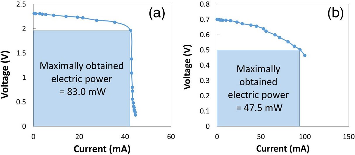
Fig. 6. Voltage-current graphs of the (a) PV cell and (b) PD by changing the load resistance when the 500 mW LD is operating at the maximum E/O conversion condition.

下载图片 查看所有图片

Based on the results presented in Table 1, Fig. 5, and Fig. 6, we can calculate the DC-to-DC transfer efficiencies of the back-to-back OWPT, EBtoB, by using Eq. (1). The results are summarized in Table 2. It should be noted that these transfer efficiencies were obtained when the optical power transmitters were operating at the maximum E/O conversion efficiencies and the optical power receivers were optimized by varying the load resistance. Through the optimization process, the maximum transfer efficiency (3.32%) was obtained when the 200 mW LD and PV cell were used as the optical power transmitter and optical power receiver, respectively.

The optimization process may look finalized. However, there are more chances for further optimization. The results in Table 2 were based on the case where the optical power transmitter was fixed at the maximum E/O conversion efficiency. However, even if the optical power transmitter is not operated at the maximum E/O conversion efficiency, it is still possible to achieve a higher OWPT efficiency if the optical power receiver shows a higher O/E conversion efficiency. Therefore, we investigated the total OWPT efficiencies by varying the condition of the optical power transmitter. For each optical output power of the LD, we optimized the optical power receiver by varying the load resistance. Figure 7 shows the E/O conversion efficiencies of the LDs, the O/E conversion efficiencies of the optical power receivers, and the total OWPT efficiencies as functions of the optical output power of the LDs. In Fig. 7, the point marked by the arrow in each figure is the point where the E/O conversion efficiency of the LD is the maximum.
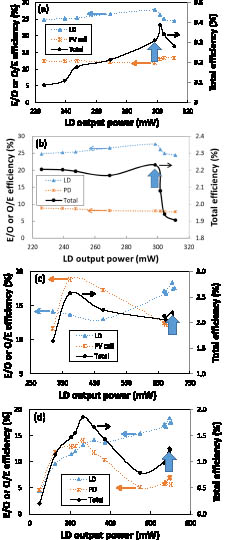
Fig. 7. E/O conversion efficiency of the LD, the O/E conversion efficiency of the optical power receiver, and the total OWPT efficiency as functions of the optical output power of the LD for the following OWPT systems: (a) 200 mW LD and PV cell, (b) 200 mW LD and PD, (c) 500 mW LD and PV cell, and (d) 500 mW LD and PD. The point marked by the arrow in each figure is the point where the E/O conversion efficiency of the LD is the maximum.

下载图片 查看所有图片

From Fig. 7, it is shown that the maximum E/O conversion efficiency of the LD does not guarantee the maximum total OWPT efficiency (i.e., the point marked by the arrow does not guarantee the maximum total OWPT efficiency). This is because the O/E efficiency of the optical power receiver can be high even if the E/O efficiency of the LD is not maximum. Therefore, the point at which the total OWPT efficiency is maximum can be another condition at which the E/O efficiency of the LD is not maximum. Therefore, the OWPT efficiencies presented in Table 2 (where the LD was fixed at the maximum E/O conversion efficiency) were not the real maximum OWPT efficiencies and they could be further optimized. The total OWPT efficiencies after the whole system optimization are summarized in Table 3.

Table 2. OWPT Efficiency When the Optical Power Transmitter Was Operating at the Maximum E/O Conversion Efficiency

Optical power transmitterCE/O (%)Optical power receiverCO/E (%)EBtoB
200 mW LD27.8PV cell11.933.32
PD8.042.23
500 mW LD18.4PV cell11.962.20
PD6.841.26

查看所有表

Table 3. Maximum OWPT Efficiency After the Whole System Optimization

Optical power transmitterCE/O (%)Optical power receiverCO/E (%)EBtoB
200 mW LD26.1PV cell12.963.39
27.8PD8.042.23
500 mW LD13.7PV cell18.82.57
13.2PD14.11.86

查看所有表

As shown in Table 3, the maximum OWPT efficiencies after the whole system optimization were improved compared with those in Table 2. For example, the OWPT efficiency obtained with the 500 mW LD and the PV cell improved from 2.20% to 2.57% with the help of the whole system optimization. After the whole system was optimized, a maximum OWPT efficiency of 3.39% was obtained when the 200 mW LD and PV cell were used as the optical power transmitter and optical power receiver, respectively.

Here we remark that the OWPT efficiency can be further improved by using a more efficient LD, PD, and PV cell. In addition, alignment between the optical power transmitter and the optical power receiver and matching the receiver aperture to the LD beam shape are also important to improve the OWPT efficiency.

In summary, we have presented an OWPT system using near-infrared LDs as the optical power transmitters and have also presented an optimization process to maximize the transfer efficiency. We used a PV cell or a PD as the optical power receiver in the experiment. The maximum transfer efficiency was achieved by optimizing the load resistance of the optical power receiver while varying the operating condition of the LD. After the whole system optimization presented here, we found that the OWPT efficiencies improved from 3.32% to 3.39%, from 2.20% to 2.57%, and from 1.26% to 1.86% (increase by 48% from the original value), depending on the OWPT system cases. This optimization process is important to achieve a high transfer efficiency in OWPT.

References

[1] LuX.WangP.NiyatoD.KimD. I.HanZ., IEEE Commun. Surv. Tuts.18, 1413 (2016).

[2] KimS.-M.KimS.-M., Opt. Eng.52, 043205 (2013).

[3] HoS. L.WangJ.FuW. N.SunM., IEEE Trans. Magn.47, 1522 (2011).IEMGAQ0018-9464

[4] KursA.KaralisA.MoffattR.JoannopoulosJ. D.FisherP.SoljacicM., Science317, 83 (2007).SCIEAS0036-8075

[5] KlineM.IzyuminI.BoserB.SandersS., in Proceedings of IEEE Applied Power Electronics Conference and Exposition (2011), p. 1398.

[6] YedavalliP. S.RiihonenT.WangX.RabaeyJ. M., IEEE Access5, 1743 (2017).

[7] KuesterD.PopovicZ., IEEE Microw. Mag.14, 47 (2013).1527-3342

[8] ShinoharaN., J. Korean Inst. Electromagn. Eng. Sci.10, 224 (2010).

[9] JinK.ZhouW., IEEE Trans. Power Electron.34, 3842 (2019).

[10] KimS.-M.ChoiJ.JungH., Chin. Opt. Lett.16, 080101 (2018).CJOEE31671-7694

[11] HeT.YangS.-H.MunozM. A.ZhangH.-Y.ZhaoC.-M.ZhangY.-C.XuP., Chin. Phys. Lett.31, 104203 (2014).CPLEEU0256-307X

[12] HaydarogluI.MutluS., J. Microelectromech. Syst.24, 155 (2015).JMIYET1057-7157

[13] FakidisJ.VidevS.KuceraS.ClaussenH.HaasH., J. Lightwave Technol.34, 3236 (2016).JLTEDG0733-8724

[14] RaaviS.ArigongB.ZhouR.JungS.JinM.ZhangH.KimH., in Proceedings of Symposium on Wireless and Microwave Circuits and Systems (WMCS) (2013), p. 1.

[15] PaniC.RayO.GhoshA.QadirZ.SarkarM. M.RejaW., in Proceedings of International Conference on Advances in Computing, Communication, and Automation (ICACCA) (2016), p. 1.

[16] SahaA.IqbalS.KarmakerM.ZinnatS. F.AliM. T., in Proceedings of Annual International Conference of the IEEE Engineering in Medicine and Biology Society (EMBC) (2017), p. 1978.

[17] PutraA. W. S.TanizawaM.MaruyamaT., IEEE Photonics Technol. Lett.31, 157 (2019).IPTLEL1041-1135

[18] LimJ.KhwajaT. S.HaJ., Opt. Express27, A924 (2019).OPEXFF1094-4087

[19] KawashimaN.TakedaK.MatsuokaH.FujiiY.YamamotoM., in Proceedings of 22nd International Symposium on Automation and Robotics in Construction (2005), p. 373.

Sung-Man Kim, Hanbit Park. Optimization of optical wireless power transfer using near-infrared laser diodes[J]. Chinese Optics Letters, 2020, 18(4): 042603.

引用该论文: TXT   |   EndNote

相关论文

加载中...

关于本站 Cookie 的使用提示

中国光学期刊网使用基于 cookie 的技术来更好地为您提供各项服务,点击此处了解我们的隐私策略。 如您需继续使用本网站,请您授权我们使用本地 cookie 来保存部分信息。
全站搜索
您最值得信赖的光电行业旗舰网络服务平台!