光学学报, 2022, 42 (17): 1712004, 网络出版: 2022-09-16
高功率激光光学元件超精密制造技术  下载: 1183次特邀综述
Ultra-Precision Manufacturing Technology of High Power Laser Optics
图 & 表
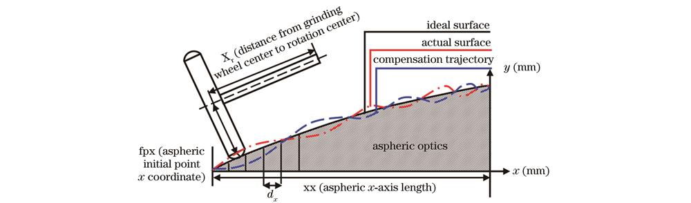
图 2. 大口径光学非球面元件超精密磨削机床
Fig. 2. Ultra-precision grinding machine for large aperture aspheric optics
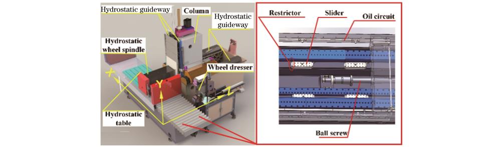
图 3. 圆弧金刚石砂轮对滚研磨修整[12]。(a)修整原理;(b)修整设备
Fig. 3. Dressing arc diamond wheel by roll abrading[12]. (a) Principle of dressing; (b) dressing equipment
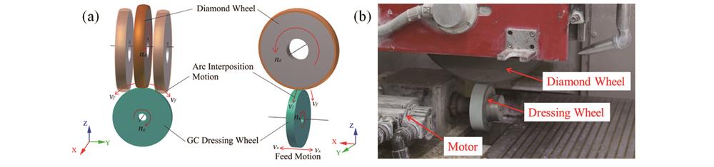
图 4. 金刚石砂轮三维形状误差在位检测和评价[13]。(a)三维形状误差在位检测原理;(b)三维轮廓误差;(c)圆度误差
Fig. 4. In-situ measurement and evaluation of 3D shape error of diamond wheel[13]. (a) Principle of in-situ measurement of 3D shape error; (b) 3D outline error; (c) roundness error
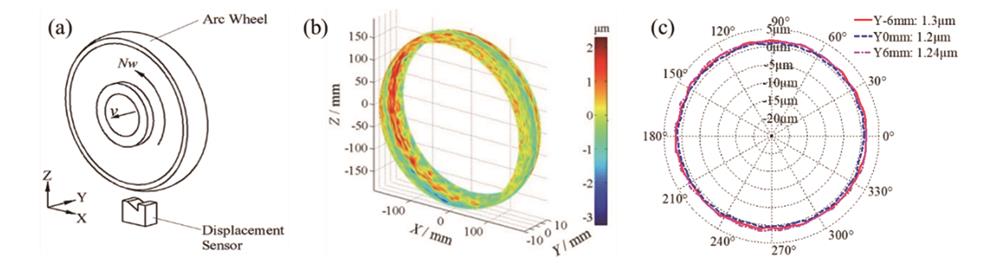
图 5. 非球面面形在位检测和补偿[5,14]。(a)在位检测轨迹;(b)在位检测实物图;(c)补偿加工原理
Fig. 5. In-situ measurement and compensation of aspheric surface shape[5,14]. (a) Trajectory of in-situ measurement; (b) physical image of in-situ detection; (c) compensation process principle
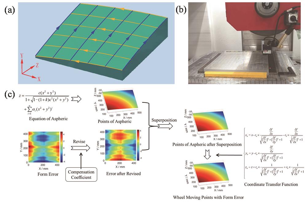
图 7. 平面快速抛光原理图与实物图。(a)原理图;(b)实物图
Fig. 7. Schematic figure and physical picture of plane rapid polishing. (a) Principle diagram; (b) physical picture
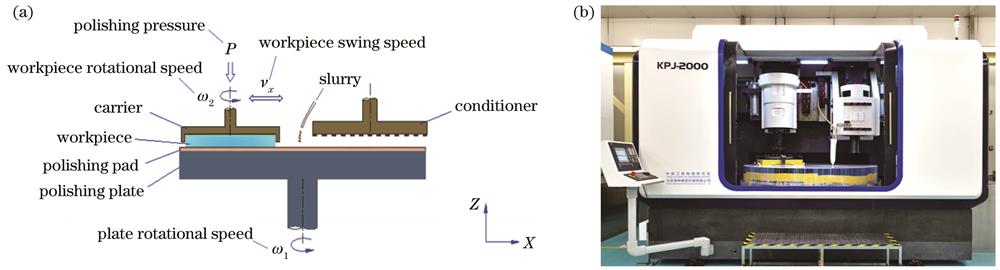
图 8. 平面快抛加工结果。(a)表面粗糙度(RMS为0.42 nm);(b)最优面形精度(PV为0.24λ)
Fig. 8. Plane rapid polishing results. (a) Surface roughness (RMS is 0.42 nm); (b) optimal profile accuracy (PV is 0.24λ)
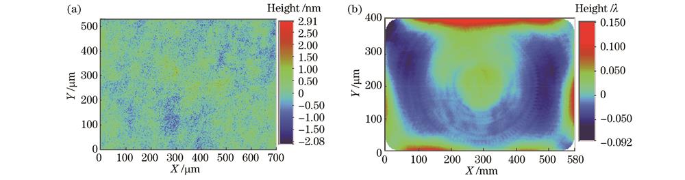
图 9. 离轴非球面镜气囊抛光实物图与原理图。(a)实物图;(b)原理图
Fig. 9. Bonnet polishing picture and principle for off-axis aspheric lens. (a) Bonnet polishing picture; (b) principle diagram
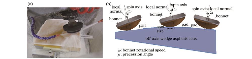
图 10. 系列化气囊工具[23]。(a)工具实物;(b)工具结构设计与仿真
Fig. 10. Serialization of bonnet tools[23]. (a) Tool picture; (b) tool structure design and simulation
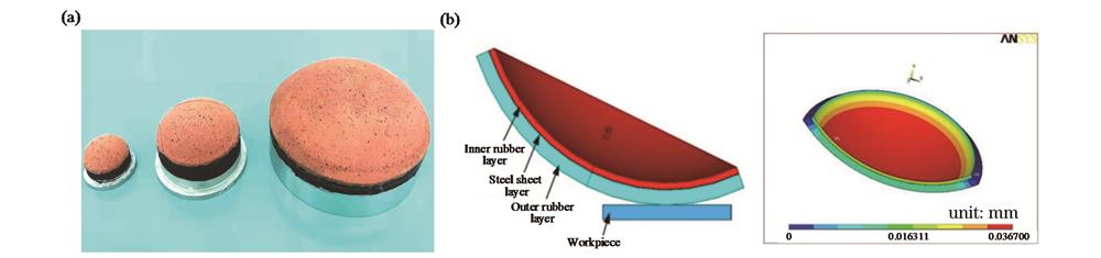
图 11. 气囊修整实物与数学模型[26]。(a)气囊修整实物;(b)气囊修整数学模型
Fig. 11. Bonnet dressing picture and mathematical model[26]. (a) Bonnet dressing picture; (b) bonnet dressing mathematical model
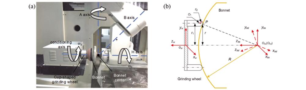
图 12. 非球面透镜气囊抛光结果。(a)初始面形;(b)保形抛亮面形;(c)快速修抛面形
Fig. 12. Results of aspheric lens by bonnet polishing. (a) Initial surface shape; (b) conformal polishing surface shape; (c) fast correction polishing surface shape
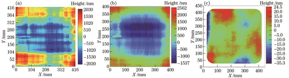
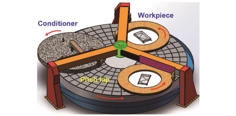
图 14. 全口径环形抛光的运动学模型。(a)运动参量;(b)轨迹弧长
Fig. 14. Kinematics model of full-aperture continuous polishing process. (a) Kinematics; (b) sliding distance
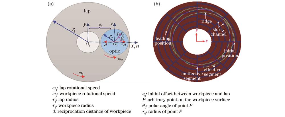
图 15. 抛光盘形状误差的检测方法和检测结果。(a)检测方法;(b)检测结果
Fig. 15. Method and result of measuring the lap shape error. (a) Measuring method; (b) measuring result
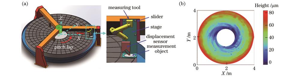
图 16. 不同工作时间的沥青盘面钝化状态图像及特征值变化曲线
Fig. 16. Passivation state images and characteristic value change curve of pitch plate for different working time
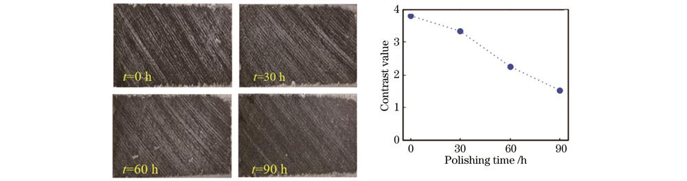
图 17. Ф5 m全口径确定性环形抛光机床以及元件加工结果。(a)机床照片;(b)元件面形结果
Fig. 17. Ф5 m full aperture deterministic continuous polisher and workpiece surface figure results. (a) Polisher photograph;(b) workpiece surface figure
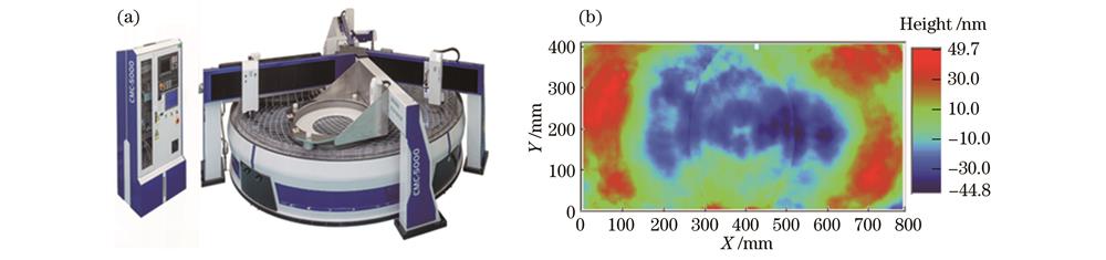
图 18. 磁流变单元技术及结果。(a)一体化随动式循环系统;(b)磁流变液流量稳定控制;(c)模块化系列抛光头(直径为20~400 mm);(d)磁流变宽范围加工能力
Fig. 18. Magnetorheological cell technology and results. (a) Integrated follow-up circulating system; (b) stable flow control of magnetorheological fluid; (c) modular series polishing head (diameter is 20-400 mm); (d) wide range magnetorheological processing capability
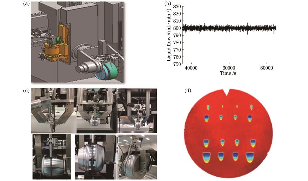
图 19. 磁流变加工连续相位板。(a)连续相位板设计图;(b)连续相位板加工残差图
Fig. 19. Continuous phase plate processed by magnetorheological method. (a) Designed continuous phase plate; (b) machining residual diagram of continuous phase plate
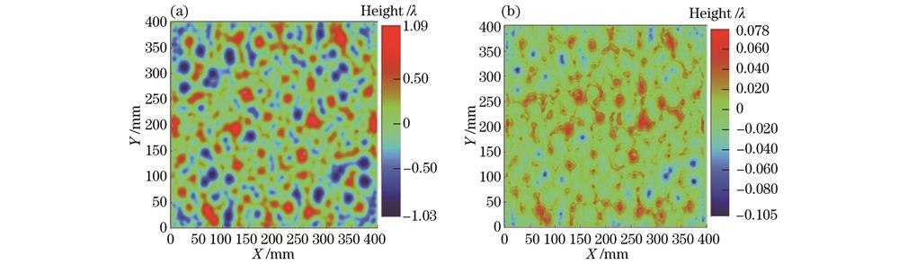
图 20. 离子束抛光机床及精密修形原理。(a)精密修形原理;(b)离子束抛光机床
Fig. 20. Ion beam polishing machine and its processing principle. (a) Principle of precision shaping; (b) ion beam polishing machine
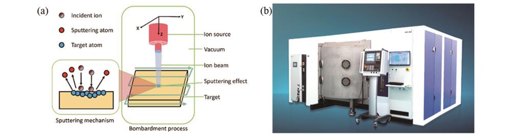
图 21. 自适应步长轨迹段划分算法示意图[54]。(a)等步长法;(b)自适应步长法
Fig. 21. Diagrams of adaptive step trajectory segment partition algorithm[54]. (a) Same step size path segment; (b) adaptive step size path segment

图 22. 离子束加工确定性验证实验。(a)原始面形(PV为0.903λ);(b)仿真结果(PV为0.360λ);(c)加工结果(PV为0.364λ)
Fig. 22. Deterministic verification experiment for ion beam polishing. (a) Original surface (PV is 0.903λ); (b) simulation result (PV is 0.360λ); (c) processed result (PV is 0.364λ)
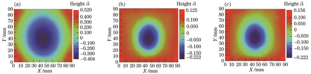
图 23. 大口径元件离子束加工结果
Fig. 23. Result of ion beam polishing for large aperture optical elements
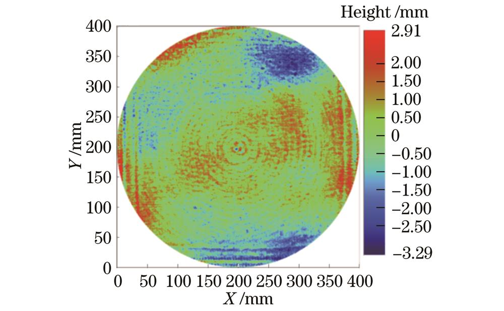
图 24. 不同路径方式模拟加工后的残余波纹[26]。(a)光栅路径(RMS为18.134 nm);(b)同心圆(RMS为18.378 nm);(c)随机路径(RMS为50.152 nm)
Fig. 24. Contours of residual ripples obtained by three paths[26]. (a) Raster path (RMS is 18.134 nm); (b) circle path (RMS is 18.378 nm); (c) random path (RMS is 50.152 nm)
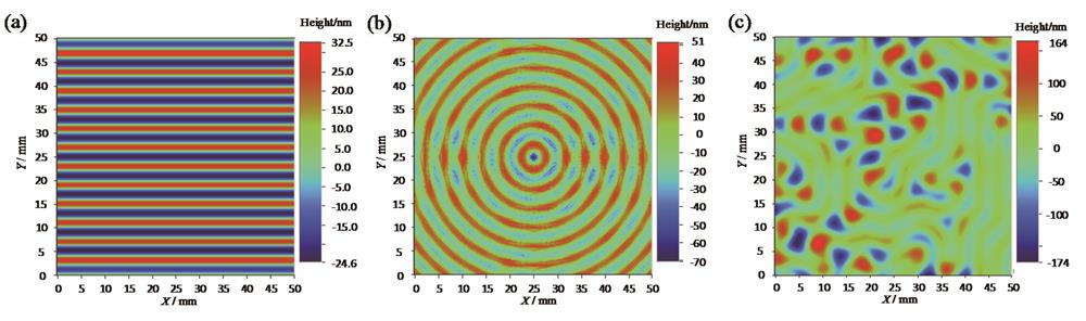
图 25. 中频误差控制工艺。(a)去除函数稳定性控制[8];(b)匀滑修正中高频误差[61]
Fig. 25. Control technology for middle frequency error. (a) Removal function stability control[8]; (b) smoothing correction for middle and high frequency errors[61]
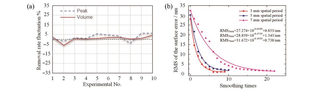
图 26. 非球面匀滑结果。(a)430 mm×430 mm非球面元件;(b)中频误差PSD1(RMS为1.67 nm)
Fig. 26. Aspheric smoothing results. (a) 430 mm×430 mm aspheric lens; (b) middle frequency error PSD1 (RMS is 1.67 nm)
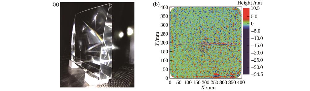
图 27. 单点金刚石飞切加工原理及飞切加工机床
Fig. 27. Schematic diagram of single point diamond fly-cutting process and fly-cutting equipment
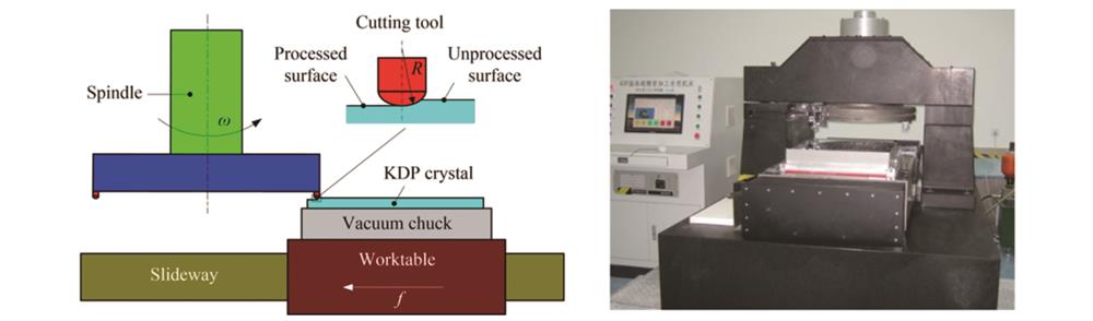
图 28. 飞切机床动态性能监测平台及仿真模型
Fig. 28. Monitoring platform and simulation model of dynamic performace of fly-cutting machine
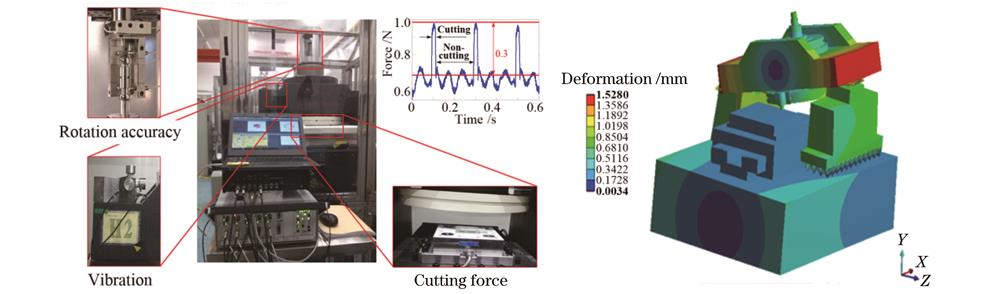
图 29. KDP晶体脆-塑转变(BDT)仿真结果[67]。(a)切削区域应力分布;(b)脆-塑转变随切削方向的变化
Fig. 29. Simulation results of BDT of KDP crystal[67]. (a) Stress state in cutting zone; (b) variation of BDT with cutting direction
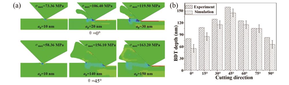
图 30. KDP晶体飞切加工表面检测结果。(a)低频误差(PV为2.1λ);(b)中频PSD1(RMS为3.14 nm);(c)中频PSD2(RMS为0.68 nm);(d)粗糙度(RMS为0.61 nm)
Fig. 30. Measurement results of KDP surface for fly-cutting. (a) Low frequency error (PV is 2.1λ); (b) middle frequency PSD1 (RMS is 3.14 nm); (c) middle frequency PSD2 (RMS is 0.68 nm); (d) roughness (RMS is 0.61 nm)
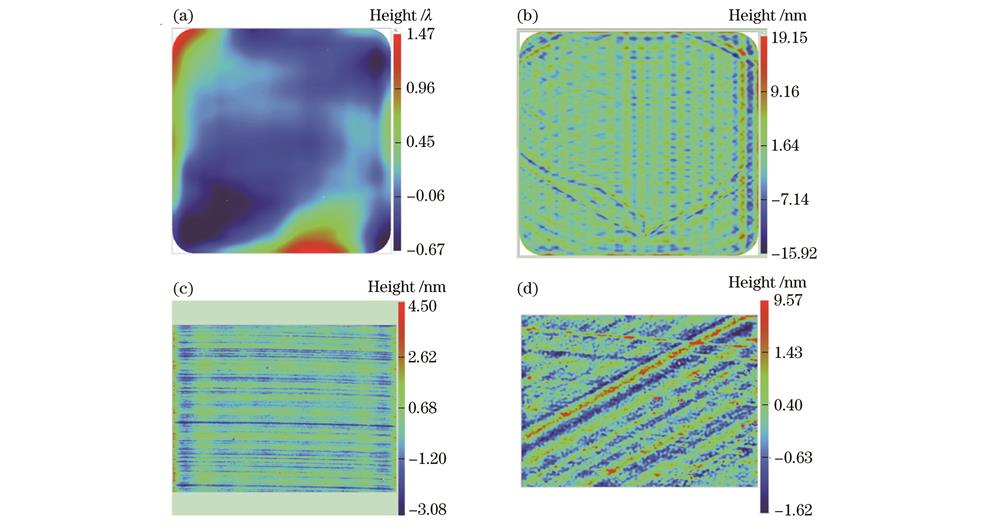
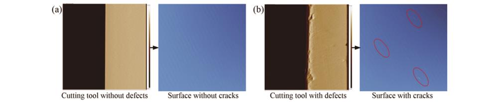
图 31. 两种典型的磨削缺陷。(a)规律性分布的虚线缺陷;(b)偶发深砂眼缺陷
Fig. 31. Two typical grinding defects. (a) Regularly distributed dotted line defects; (b) occasional deep pit defect
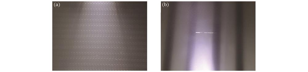
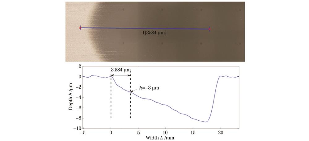
图 33. 氧化铈抛光颗粒形貌及其粒度分布图。(a)颗粒形貌图;(b)粒度分布图
Fig. 33. Morphology and particle size distribution of ceria polishing particles. (a) Particle morphology; (b) particle size distribution diagram
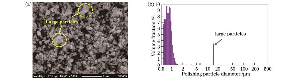
图 34. 不同方法处理后的熔石英表面金属元素含量[82]。(a)采用HF/BOE刻蚀后的铈元素含量;(b)采用HNO3刻蚀后的金属元素含量
Fig. 34. Content of metallic elements on surface of fused silica treated by different methods[82]. (a) Ce content after HF/BOE etching; (b) metallic element content after HNO3 etching
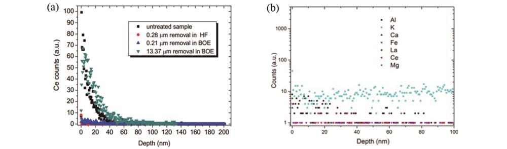
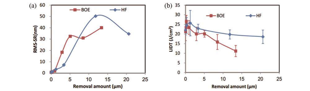
图 35. 化学刻蚀深度对熔石英元件的表面粗糙度和激光损伤阈值的影响[83]。(a)表面粗糙度;(b)激光损伤阈值
Fig. 35. Effect of chemical etching depth on surface roughness and laser damage threshold of fused silica[83]. (a) Surface roughness;(b) laser damage threshold
许乔, 陈贤华, 汪圣飞, 钟波, 谢瑞清, 王健. 高功率激光光学元件超精密制造技术[J]. 光学学报, 2022, 42(17): 1712004. Qiao Xu, Xianhua Chen, Shengfei Wang, Bo Zhong, Ruiqing Xie, Jian Wang. Ultra-Precision Manufacturing Technology of High Power Laser Optics[J]. Acta Optica Sinica, 2022, 42(17): 1712004.


 PDF全文
PDF全文

