中国激光, 2023, 50 (9): 0907106, 网络出版: 2023-03-06
激光散斑衬比血流成像关键技术及应用研究进展  下载: 1232次
Advances in Laser Speckle Contrast Imaging: Key Techniques and Applications
图 & 表
图 4. 不同算法的实验结果对比[98]。(a)tLSCI(时间衬比分析法);(b)sLSCI(空间衬比分析法);(c)stLSCI(时空联合衬比分析法);(d)savgtLSCI(空间平均衬比分析法);(e)tavgsLSCI(时间平均衬比分析法);(f)aLSCI;(g)不同算法的对比度噪声比
Fig. 4. Comparative experimental results of different algorithms[98]. (a) tLSCI algorithm; (b) sLSCI algorithm; (c) stLSCI algorithm; (d) savgtLSCI algorithm; (e) tavgsLSCI algorithm; (f) aLSCI algorithm; (g) contrast-to-noise ratio (CNR) of different algorithms

图 5. 基于特征值分解的LSCI滤波算法模型[64](
Fig. 5. LSCI filtering model based on eigenvalue-decomposition[64] (
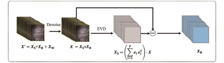
图 6. 基于特征值分解和空间滤波相结合的LSCI滤波算法[100]
Fig. 6. LSCI filtering algorithm based on eigenvalue-decomposition and filtering[100]
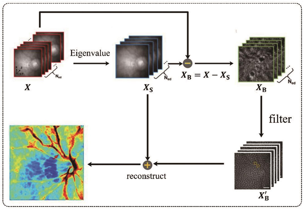
图 7. 对比实验结果[100]。(a)原始的眼底衬比图;(b)使用特征值分解和空间滤波处理后的眼底衬比图
Fig. 7. Comparative experimental results[100]. (a) Raw fundus contrast image; (b) fundus contrast image after eigenvalue-decomposition and spatial filtering
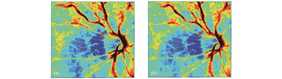
图 9. 不同去噪算法的实验结果[47]。(a)原始图,PSNR为18.5,MSSIM为0.46,R=0.813;(b)savg-tLSCI算法,PSNR为32.8,MSSIM为0.87,R=0.987;(c)NLM算法,PSNR为31.0,MSSIM为0.90,R=0.986;(d)BM3D算法,PSNR为35.8,MSSIM为0.92,R=0.993;(e)MD-ABM3D算法,PSNR为37.8,MSSIM为0.96,R=0.996;(f)参考图
Fig. 9. Output of different denoising algorithms[47]. (a) Original image, where PSNR is 18.5, MSSIM is 0.46, and R is 0.813; (b) savg-tLSCI algorithm, where PSNR is 32.8, MSSIM is 0.87, and R is 0.987; (c) NLM algorithm, PSNR is 31.0, MSSIM is 0.90, and R is 0.986; (d) BM3D algorithm, PSNR is 35.8, MSSIM is 0.92, and R is 0.993; (e) MD-ABM3D algorithm, PSNR is 37.8, MSSIM is 0.96, and R is 0.996; (f) reference image
图 11. rLASCA算法的实验结果[61]。(a)未配准的散斑衬比图像;(b)rLASCA算法配准后的散斑衬比图像;(c)图(a)中白色矩形框区域的放大图;(d)图(b)中白色矩形框区域的放大图;(e)白色矩形框区域的白光图
Fig. 11. Experimental results of rLASCA algorithm[61]. (a) Unregistered laser speckle contrast image; (b) laser speckle contrast image registered by rLASCA; (c) enlarged image of white rectangular box area in figure (a); (d) enlarged image of white rectangular box area in figure (b); (e) white light map of white rectangular box area
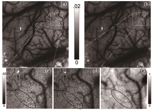
图 12. 基于非相干光的非刚体配准算法[45]。(a)双模态照明装置;(b)算法模型
Fig. 12. Non-rigid registration algorithm based on non-coherent light[45]. (a) Experimental setup of dual-mode lighting system; (b) algorithm model
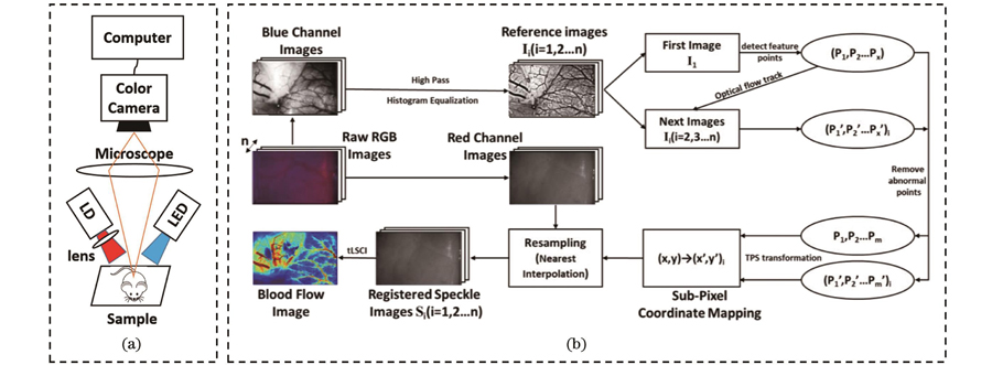
图 13. 刚性配准与非刚性配准结果的对比[45]。(a)未配准的血流图像;(b)血流图像的刚性配准结果;(c)血流图像的非刚性配准结果
Fig. 13. Comparison of rigid registration and non-rigid registration[45]. (a) Unregistered blood flow image; (b) blood flow image after rigid registration; (c) blood flow image after non-rigid registration
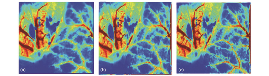
图 14. 基于图像分解的LSCI运动伪影的校正模型[106]。(a)校正模型;(b)选取回归参量;(c)回归拟合分析;(d)~(f)校正前后的衬比值
Fig. 14. Correction model for LSCI movement artifact based on image decomposition[106]. (a) Correction model; (b) selection of regression variance; (c) fitted by regression analysis; (d)-(f) contrast value before and after movement correction

图 15. 基于轮廓波变换和多聚焦图像融合算法的LSCI校正模型[46]
Fig. 15. LSCI correction model based on contourlet transform and multi-focus image fusion[46]
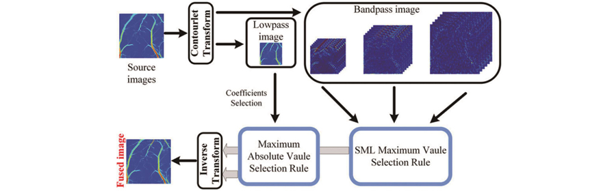
图 16. 不均匀光强校正前后的结果[103]。(a)受不均匀性影响的衬比图像;(b)重建后的衬比图像
Fig. 16. Experiment results before and after nonuniform intensity correction[103]. (a) Contrast image affected by nonuniformity; (b) reconstructed contrast image
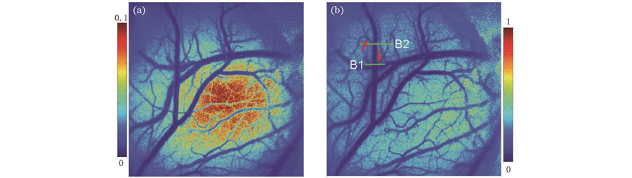
图 17. 非均匀校正实验结果[110]。(a)两种不同光照强度下的灰度散斑图像;(b)从上往下依次是高强度光照、低强度光照下的衬比图以及校正后的低强度光照衬比图;(c)低强度光照、高强度光照以及校正后低强度光照衬比图沿图(a)中横向红线的衬比值曲线;(d)校正后低强度光照衬比图沿图(a)中纵向黄线的衬比值曲线
Fig. 17. Experimental results of nonuniform correction[110]. (a) Grayscale speckle images at two different intensities; (b) from the top to the bottom: contrast maps at high intensity and low intensity and corrected contrast map at low intensity; (c) contrast profile along the red line marked in figure (a) of contrast maps at low intensity and high intensity and corrected contrast map at low intensity; (d) contrast profile along yellow line marked in figure (a) of corrected contrast map at low intensity
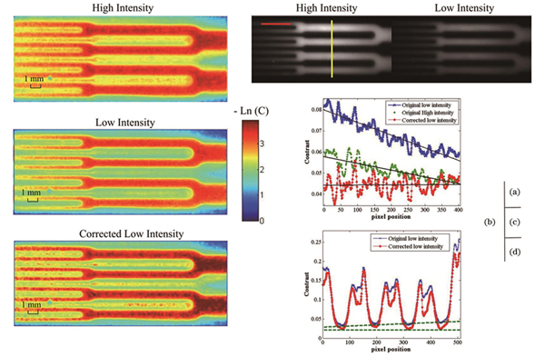
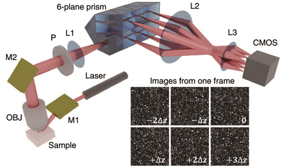
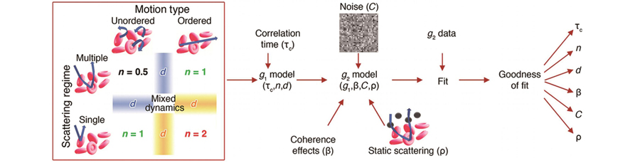
图 21. 空间频域成像LSCI[121]。(a)si-SFDI实验装置;(b)si-SFDI算法流程
Fig. 21. Spatial frequency domain imagingLSCI[121]. (a) Experimental setup of si-SFDI; (b) processing flow of si-SFDI

图 24. 基于样本熵的衬比分析方法及部分实验结果[111]。(a)基于样本熵的衬比分析方法;(b)部分实验结果
Fig. 24. Sample entropy-based laser speckle contrast analysis method and partial experimental results[111]. (a) Sample entropy-based laser speckle contrast analysis method; (b) partial experimental results
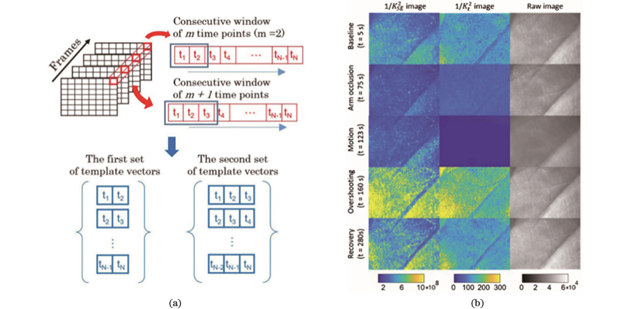
图 25. 多曝光激光散斑成像[83]。(a)MESI系统;(b)单曝光成像和MESI下τc的百分比偏差
Fig. 25. Multi-exposure laser speckle imaging[83]. (a) Multi-exposure speckle imaging system; (b) percentage deviation in
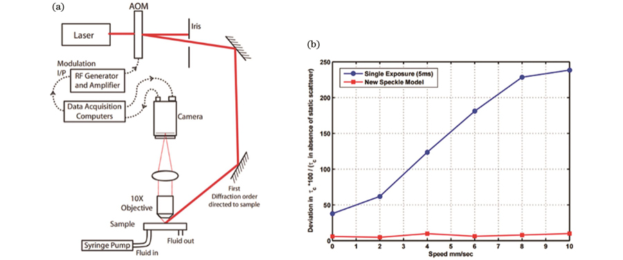
图 26. 非宽场照明的横向激光散斑对比分析方法[127]。(a)线性扫描照明的横向激光散斑成像系统;(b)图像处理流程;(c)~(e)传统衬比分析方法、使用常数加权的横向散斑衬比分析方法、使用深度灵敏度曲线加权的横向散斑衬比分析方法获得的血流图像
Fig. 26. Lateral speckle contrast analysis method combined with non-wide field illumination[127]. (a) Schematic of LSCI experimental setup based on line beam scanning illumination; (b) image processing flow; (c)-(d) blood flow images obtained by traditional contrast analysis method, lateral speckle contrast analysis methods weighted with constant and depth sensitivity curves, respectively
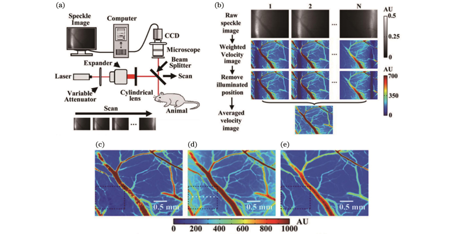

图 28. 激光散斑血流成像系统[130]。(a)TR-LSCI成像系统;(b)传统的反射式成像系统
Fig. 28. LSCI system for blood flow[130]. (a) TR-LSCI system; (b) conventional reflective-detected LSCI system
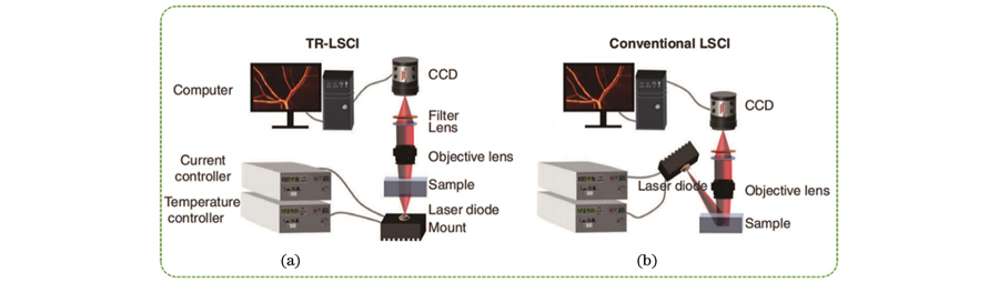
图 29. 新型LSCI系统及其应用研究进展
Fig. 29. Novel LSCI systems and their advances in application and research
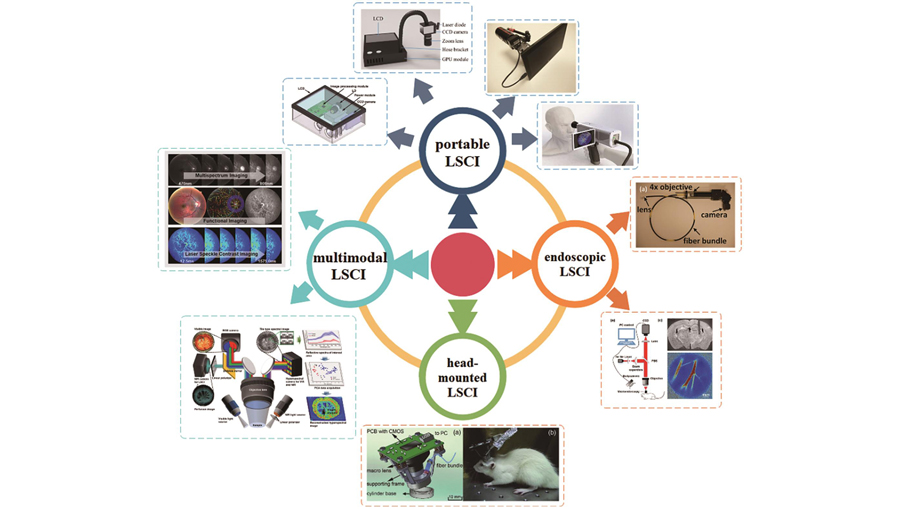
图 30. 基于DSP的便携式LSCI系统[135]。(a)便携式LSCI系统示意图;(b)硬件框架图;(c)软件架构图
Fig. 30. Portable LSCI based on DSP[135]. (a) Schematic illustration of portable LSCI system; (b) block diagram of hardware framework; (c) block diagram of software framework
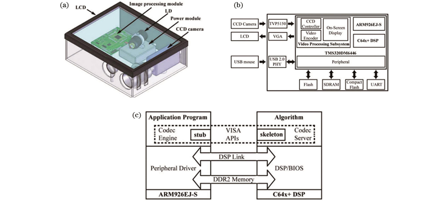
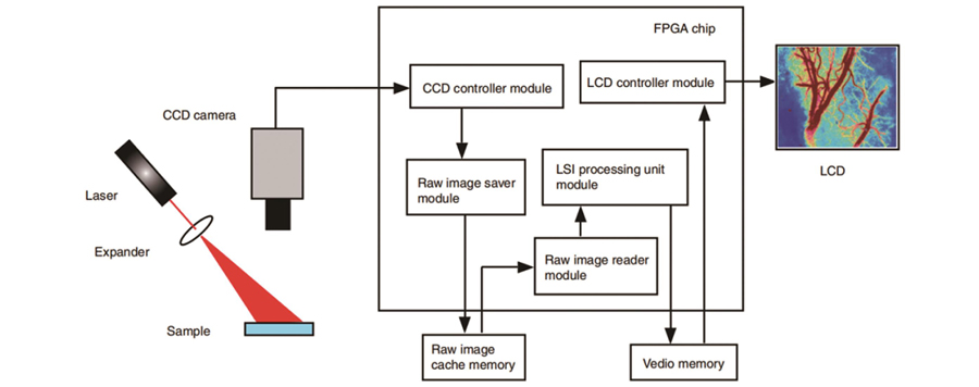
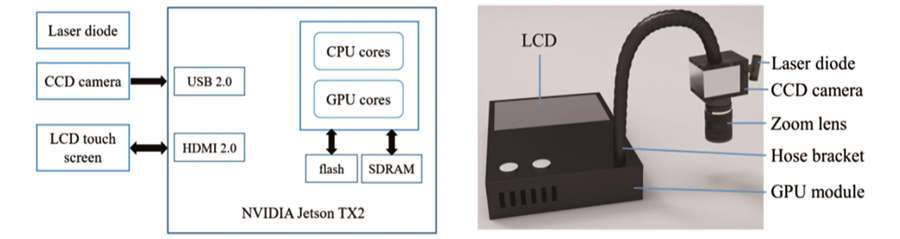
图 34. 腹腔镜LSCI双显示成像系统[14]。(a)腹腔镜LSCI成像系统;(b)插入腹腔镜;(c)手持式操作过程;(d)LSCI肠成像;(e)LSCI胆囊成像;(f)LSCI肠系膜成像
Fig. 34. Dual-display laparoscopic laser speckle contrast imaging (LSCI) system[14]. (a) Laparoscopic LSCI system; (b) inserted laparoscopy; (c) handheld operation; (d) LSCI bowel imaging; (e) LSCI gallbladder imaging; (e) LSCI mesentery imaging
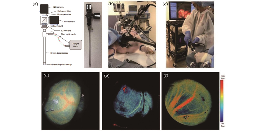
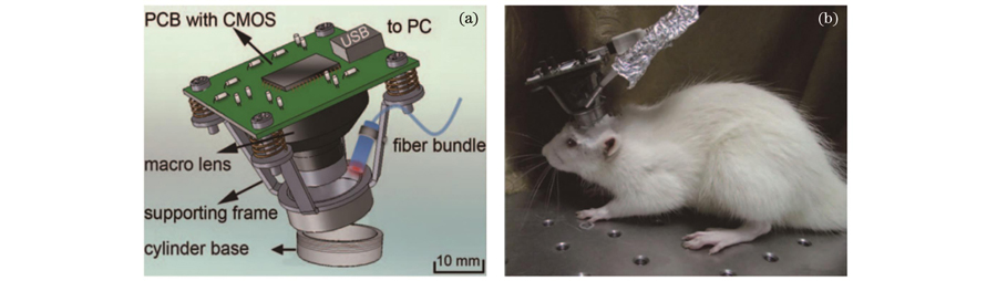

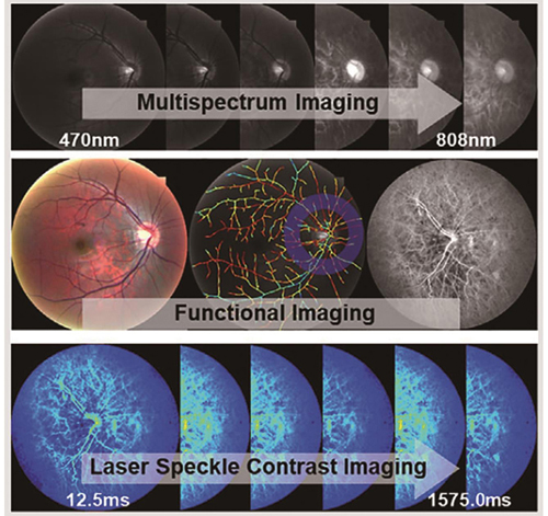
表 1动态散斑衬比值校正模型[115]
Table1. Correction model of dynamic speckle contrast[115]
|
表 2不同散射特性和粒子运动模式的电场自相关函数[73]
Table2. Electric field autocorrelation function
|
翟林君, 傅玉青, 杜永兆. 激光散斑衬比血流成像关键技术及应用研究进展[J]. 中国激光, 2023, 50(9): 0907106. Linjun Zhai, Yuqing Fu, Yongzhao Du. Advances in Laser Speckle Contrast Imaging: Key Techniques and Applications[J]. Chinese Journal of Lasers, 2023, 50(9): 0907106.


 PDF全文
PDF全文

