激光与光电子学进展, 2022, 59 (9): 0922019, 网络出版: 2022-05-10  

面向光刻机晶圆台的超精密光栅定位技术 下载: 3392次特邀综述

Ultraprecision Grating Positioning Technology for Wafer Stage of Lithography Machine
作者单位
1 清华大学深圳国际研究生院,广东 深圳 518055
2 清华-伯克利深圳学院,广东 深圳 518055
摘要

光栅干涉仪凭借高精度和高鲁棒性,成为先进节点光刻机中的重要定位装置。针对14 nm及以下节点光刻机晶圆台的定位需求,综述了多自由度纳米/亚纳米测量精度的零差式和外差式光栅干涉仪的发展,并介绍了“四光栅-四读数头”的光刻机六自由度位移测量系统布局。为了获得更高的精度和可溯源性,综合分析了光栅干涉仪中的环境误差、安装误差和仪器内在误差,并提出了光栅干涉仪实现亚纳米测量精度的关键问题,期望为光栅干涉仪精度提升和系统搭建提供初步指导。

Abstract

Grating interferometers are becoming important positioning instruments in advanced node lithography machines owing to their high precision and robustness. To meet ultrahighly accurate positioning demands in the worktable of ≤14-nm node lithography machines, homodyne and heterodyne grating interferometry technologies and core systems with multidegree-of-freedom (multi-DOF) and nano/subnanometer metric accuracy were reviewed. Furthermore, a six-DOF positioning system in a current lithography machine enabled by an optimal configuration of “four gratings-four reading heads” was illustrated. Finally, errors in grating interferometers, including environmental error, installation error, and instrument inherent error were briefly discussed, and key challenges in error modeling, separation, and compensation were reviewed for achieving subnanometric accuracy and long-term accuracy stability. Hopefully, this study can provide preliminary guidelines for improving the accuracy and constructing various systems of grating interferometers.

1 引言

集成电路(IC)产业作为支撑国家经济发展和保障****的战略性、基础性和先导性产业之一,是新一代信息技术产业的核心。2021年,我国集成电路进口总额为2.7万亿元,规模远超原油进口总额(1.6万亿元),集成电路装备的国产化迫在眉睫1。光刻是集成电路制造中最复杂、最关键的工艺步骤,光刻机作为关键设备,研发的技术门槛和资金门槛高,最先进的5~3 nm光刻机仅有荷兰ASML可以生产。国内技术领先的上海微电子装备有限公司已量产的光刻机中性能最优的是90 nm光刻机,28 nm光刻机仍在研制中,与国际高端光刻机在节点上有非常大的差距。全行程大于300 mm的晶圆台是光刻机的三大核心部件之一,针对全行程晶圆台的超精密定位技术是光刻机中的关键核心技术。

激光干涉仪和光栅干涉仪是当前光刻机晶圆台精密定位的两条重要技术路线。激光干涉仪以激光波长为基准,具有高精度和可溯源性,是超精密定位常用的装置。为了测量晶圆台多自由度位移,需采用多台激光干涉仪搭建多自由度测量系统。由于激光干涉仪的光路较长,即使采取环境补偿,激光干涉仪仍存在纳米级的死程误差2-4。此外,多台激光干涉仪的光路难以保证对准到空间中同一个点,会产生阿贝误差和余弦误差,不利于测量精度5-8。因此在光刻机晶圆台中,激光干涉仪被光栅干涉仪部分替代9-10。另一方面,光栅干涉仪以光栅栅距为基准,利用光栅的衍射效应易于实现单点多自由度测量。由于光栅干涉仪的光路较短,具备更高的环境鲁棒性,适合光刻机六自由度超精密定位的需求。

本文首先介绍14 nm及以下节点光刻机晶圆台的定位需求,之后根据光栅干涉仪的研究现状,综述多自由度纳米/亚纳米精度光栅干涉测量系统的发展,并对面向光刻机需求的光栅干涉仪布局进行介绍,最后详述了光栅干涉仪精度和误差分析的关键问题。

2 先进节点光刻机晶圆台的定位需求

套刻误差是光刻机的重要性能指标之一。14 nm节点光刻机(“节点”术语在28 nm后,代指一代半导体技术工艺)的套刻误差要求小于5.7 nm11。从IEEE 2021年版的国际设备和系统蓝图中可以得到,“7 nm”节点的套刻误差最大为3.5 nm,“5 nm”节点为3 nm,“3 nm”节点为2.4 nm,“2.1 nm”节点为2 nm,“1.5 nm”节点为1.6 nm12。由于光刻机中的光源系统十分庞大,由曝光台和测量台组成的晶圆台承载硅片完成进给运动,如[图1(a)、(b)]所示9。因此,影响套刻误差的一个重要因素是光刻机晶圆台的定位精度,且定位误差在误差分配中通常占总套刻误差的十分之一,即对于“14 nm”节点,定位精度应优于0.57 nm。光刻机晶圆台基于磁悬浮,其运动由三个平面运动自由度XYZ和三个旋转自由度θXθYθZ组成,如[图1(c)、(d)]所示,因此测量系统需对其完成六自由度的位移测量,且XY两个平面自由度需实现大行程测量13-14

图 1. 光刻机晶圆台及六自由度定位示意图。(a)光刻机系统示意图;(b)光刻机晶圆台;(c)晶圆台精密位移部件误差源;(d)六自由度运动误差示意图

Fig. 1. Schematic diagrams of wafer stage and six-degree-of-freedom positioning in lithography machine. (a) Schematic diagram of lithography system; (b) photo of worktable of lithography machine; (c) error sources of precision displacement parts of worktable; (d) schematic diagram of six-degree-of-freedom motion error

下载图片 查看所有图片

表 1. 先进节点14 nm光刻机晶圆台需满足的性能要求

Table 1. Performance requirements for advanced node 14 nm lithography machine workpiece stage

PerformanceInformationDescription
Range>300 mmIn X- and Y-directions
Degree of freedom(DOF)Six-DOFX·Y·Z·θX·θY·θZ
AccuracyBetter than 0.57 nmFor the process with smaller node,the measurement accuracy should be better
Velocity>1 m/sHigh dynamic measurement

查看所有表

光刻机晶圆台的定位需求如表1所示,其中先进节点光刻机晶圆台对测量精度、测量自由度、测量范围及测量速度都提出了极高的要求。

当前,光刻机晶圆台通常采用多轴双频激光干涉仪测量其六自由度位移。[图2(a)]为典型的基于多轴双频激光干涉仪的测量方案,为了在晶圆台的侧面布置多轴激光干涉仪,需在晶圆台上安装长条反射镜;通过多个激光干涉仪的读数解算出晶圆台的六自由度位移10。然而,随着测量误差、测量行程、测量速度等指标的不断提高,双频激光干涉仪由于测量精度易受环境影响、较重的长条镜导致晶圆台动态性能差等问题难以满足日益提升的测量需求515-17。ASML公司NXT1950I光刻机所用激光干涉仪噪声水平为0.9 nm,如[图2(a)]所示。而光栅干涉仪的测量基准为光栅栅距,暴露在环境中的光路较短,如[图2(b)]所示,光栅干涉仪的噪声水平为0.22 nm,根据IEEE 2021年版的国际设备和系统蓝图,其有能力应用于5 nm和3 nm节点的光刻机中。相比于激光干涉仪,光栅干涉仪的测量方案,依赖于刻画在基底表面的物理刻度,长期稳定性好,具有安装便利、质量轻盈等优点,在14 nm及以下节点光刻机中,已部分取代多轴激光干涉仪测量系统。但是光栅干涉仪面临多自由度测量的实现、亚纳米精度的保持、大行程的可实现性等多种挑战。

图 2. 荷兰ASML光刻机所用的激光干涉仪与光栅干涉仪测量系统对比。(a)激光干涉仪测量系统;(b)光栅干涉仪测量系统

Fig. 2. Comparison of laser interferometer and grating interferometer measurement system used by ASML lithography machine in the Netherlands. (a) Laser interferometer measurement system; (b) grating interferometer measurement system

下载图片 查看所有图片

综上所述,发展先进的光栅干涉测量技术,解决测量范围、精度、动态性之间的固有矛盾,进而实现光刻机晶圆台的超精密定位测量,解决光刻机的核心瓶颈,对于实现光刻机的全面国产化,促进电子信息产业的良性发展,具有重大的意义。

3 超精密光栅定位技术

光栅干涉仪属于光栅编码器的一种,其使用的是栅距小于20 μm的衍射光栅。光栅干涉仪基于光栅衍射光多普勒频移产生的干涉条纹变化,对干涉信号解耦实现位移测量18-21。根据测量自由度分类,光栅干涉仪可以分为单自由度光栅干涉仪、二自由度光栅干涉仪和多自由度光栅干涉仪。当前单自由度光栅干涉仪和二自由度面内光栅干涉仪的技术较为成熟,已有商用产品,例如Magnescale的激光尺和Heidenhain KGM系列等,而多自由度光栅干涉仪,包括三自由度和六自由度的光栅干涉仪仍处于研发中,未实现小型化和集成化。根据测量原理,光栅干涉仪可以分为零差干涉测量和外差干涉测量。零差干涉使用单频激光,其干涉信号是一个强度随着位移而变化的信号,但是容易受到光功率变化、环境波动等影响造成信号强度变化,从而产生误差,此外单个零差干涉信号无法辨别运动方向,因此需要通过移相光路产生90°相移以实现辨向22-26,增大了干涉仪体积。外差干涉仪使用双频激光,其信号是一个相位随着位移变化的拍频信号,利用拍频信号解耦相位得到位移信息,拍频信号抗干扰能力较强,有利于超高精度测量27-28。但是,外差干涉测量的频差会影响到测量速度29-30,高频差的声光/电光调制器会提高成本,此外由于光学器件的非理想化,会造成频率混叠引起误差31-32

3.1 高精度光栅干涉仪及面内XY二自由度测量的发展

光栅干涉仪从最初的基于一维衍射光栅发展而来,基本原理如[图3(a)]所示,将光栅的正负一级衍射光合光产生干涉,光栅移动带入的多普勒频移通过干涉信号的强度变化解调出来,进而实现微小位移的测量33。目前单自由度光栅干涉仪主要的精度提升手段有两个:1)采用更小的光栅周期和更高的光学细分,将信号周期尽可能降低,可以到0.017 nm的分辨率,如[图3(b)]所示34;2)结构上采用自准直入射方式,这样系统对于沿光栅法线方向的移动不敏感,可以提升测量的稳定性,如[图3(c)]所示35

图 3. 高精度光栅干涉仪基本原理和亚纳米测量方案。(a)一维衍射光栅位移测量原理;(b)Magnescale光栅干涉仪;(c)自准直结构光栅干涉仪

Fig. 3. Basic principle of high precision grating interferometer and sub-nano measurement scheme. (a) Principle of one dimensional diffraction grating displacement measurement; (b) Magnescale grating interferometer; (c) self-collimating grating interferometer

下载图片 查看所有图片

虽然单自由度光栅干涉仪能够达到亚纳米的精度,但是需在采用层叠式的运动台上使用,不适用于光刻机等需要多自由度定位的场合。为解决多自由度测量的难题,能同时测量两个位移自由度上的运动量的二自由度光栅干涉仪被开发出来。夏豪杰36提出的二自由度光栅干涉仪采用两个直交方向上槽型一致的二维衍射光栅,基于单频激光零差干涉的原理,在两个衍射方向上分别获取多普勒频移产生的相位变化,从而解算出两个方向上的位移,如图4所示。基于这种原理的产品已见诸于世,典型代表如Heidenhain的KGM系列、VM系列,Optra的Nanogrid,图5为Heidenhain KGM 282二自由度光栅干涉仪37

图 4. 二自由度光栅干涉仪

Fig. 4. Two-degree-of-freedom grating interferometer

下载图片 查看所有图片

图 5. Heidenhain公司开发的KGM 282二自由度光栅干涉仪37

Fig. 5. KGM 282 two-degree-of-freedom grating interferometer developed by Heidenhain company[37]

下载图片 查看所有图片

为了实现绝对测量,Li等38-40对二维平面光栅进行绝对编码,通过结合增量码道和绝对码道的方法实现了平面二自由度的准绝对式测量,如图6所示,该编码器可在16 mm的行程下实现10 nm的重复性。

图 6. 绝对式位移测量原理图

Fig. 6. Schematic of absolute displacement measurement

下载图片 查看所有图片

同时,为了进一步提升干涉信号的质量,提升对环境波动的抵抗能力,基于外差干涉的原理的二自由度光栅尺也陆续被提出来,其基本原理如图7所示,采用双频激光作为光源,以拍频信号作为探测信号,这些研究机构包括国防科技大学41、清华大学42等。

图 7. 基于二维光栅的面内XY二自由度光栅干涉仪

Fig. 7. XY two-degree-of-freedom grating interferometer based on two-dimensional grating

下载图片 查看所有图片

平面二自由度光栅干涉仪在实现二自由度测量中,对于解决阿贝误差、降低测量系统尺寸等方面都有很好的作用,但是由于无法实现面外自由度Z的测量,其仍然无法满足当前光刻机晶圆台六自由度的定位要求。不过,值得注意的是,其为多自由度测量的光栅干涉仪研发提供了有益的借鉴。

3.2 具有面外位移测量能力的XYZ三自由度光栅干涉仪

根据上文所述,基于二维平面光栅搭建平面位移测量系统可以有效克服阿贝误差,实现多自由度测量,利于结构紧凑化。在上述的结构上加以丰富和改进,基于二维平面光栅可以搭建三自由度和六自由度测量系统,实现面内位移XY和面外位移Z的测量及三个角位移的测量。因此,基于二维光栅的干涉测量系统有能力满足光刻机高精度多自由度的测量需求。

3.2.1 零差干涉

零差干涉式光栅干涉仪基于单频激光干涉原理,其产生的信号是直流信号,通过信号的幅值周期性变化解算得到位移。基于零差干涉技术可以构造多自由度光栅测量系统。为了实现面外位移的测量,日本东北大学的Kimura等23提出了一种新型的三自由度位移测量方法,该方法能够同时测量XYZ三个方向的位移,如[图8(a)]所示。

图 8. 基于二维光栅的具有面外测量能力的XYZ三自由度光栅干涉仪。(a)三自由度光栅干涉仪;(b)自准直结构三自由度光栅干涉仪

Fig. 8. XYZ three-degree-of-freedom grating interferometer with out of plane measurement capability based on two-dimensional grating. (a) Three-DOF grating interferometer; (b) three-DOF grating interferometer with self-collimating structure

下载图片 查看所有图片

该方法采用双光栅结构,来自参考光栅和测量光栅的衍射光干涉,测量光栅的三自由度移动会使得干涉信号发生变化,通过解析干涉信号,获取三自由度位移。合理设计光栅参数和电路细分,可以得到亚纳米的分辨率。其优势在于仅有一个测量点,容易扩展到多读数头分布式布置。但需指出,该系统在Z向的位移测量,有一定限制,过大的Z位移会导致探测器上的光斑移动,测量信号减弱,Z向测量范围一般在1 mm以内。这对于平面运动中微小的Z向误差运动是足够的。随后,国内哈尔滨工业大学Lin等43于2017年提出了能够拓展Z向位移的XYZ三自由度光栅干涉仪,如[图8(b)]所示,该干涉仪采用自准直入射的方式,其好处在于Z轴的变化不会引起光斑的移动,可以显著提升Z轴测量范围。

3.2.2 外差干涉

外差三自由度光栅干涉仪目前主要有两个技术路线,一种是哈尔滨工业大学林杰等44提出的方法,该方法采用了与[图8(b)]类似的布局方式,但是光源改为了双频激光,如图9所示。但是,在该设计中,Z向位移所引入的相位变化无法与原始拍频信号解耦。另一种解决方案主要通过在平面XY二自由度外差光栅干涉仪中增加一轴激光干涉仪的方式来实现,如图10所示,这种方法充分运用了干涉信号的特点,具有可行性45

图 9. 基于双光栅的外差三自由度光栅干涉仪

Fig. 9. Heterodyne three-degree-of-freedom grating interferometer based on two gratings

下载图片 查看所有图片

图 10. 基于单光栅共光路的外差三自由度光栅干涉仪

Fig. 10. Heterodyne three-degree-of-freedom grating interferometer with single grating and common optical path

下载图片 查看所有图片

3.3 六自由度光栅干涉仪

如何实现六自由度高精度测量,是精密测量领域国际公认的一个难题。无论是基于零差干涉原理,还是基于外差干涉原理,六自由度测量系统结构往往复杂。当前的六自由度测量方案可以分为单测量点六自由度测量系统和多测量点六自由度测量系统。

3.3.1 单测量点六自由度测量系统

研究人员在[图8(a)]的基础上,又对三个自由度的转角误差(θXθYθZ)的同时测量开展了研究,提出了基于光栅的三自由度激光自准直仪46。三自由度角度测量系统中,传统的镜面反射面被光栅面取代,绕入射光轴的转动则可以通过正负一级衍射光的不同移动量来计算。并将该三自由度激光自准直仪与[图8(a)]所示的三自由度光栅干涉仪结合,形成了如图11所示的单测量点六自由度测量系统,该系统在平动方向达到了1 nm的分辨率,角度分辨率优于0.3"。但是该系统依赖于光学元件的性能,分光和滤光的不完善将会导致轴间串扰47

图 11. 单测量点六自由度测量系统

Fig. 11. Single-measuring-point six-degree-of-freedom measuring system

下载图片 查看所有图片

3.3.2 多测量点六自由度测量系统

在多测量点冗余合成六自由度方面,研究人员提出的三光束-六自由度测量系统如[图12(a)]所示。每个光束均可以测量三自由度位移(XYZ),转角量(θXθYθZ)由三个光束的位移差来解算48。同一测量光路,光程一致,对外界干扰的响应一致,有利于动态测量。但问题在于,光栅的面积不能有效利用,三个测量点的光强和偏振需要一致,同时小周期、大面积二维光栅的获取较为困难。在读数头设计方面:动态数据的切换等问题需要解决。

图 12. 多测量点六自由度测量系统。(a)基于二维光栅的三光束-六自由度测量系统;(b)两测点-三测量单元的六自由度测量系统

Fig. 12. Multi-measuring-point six-degree-of-freedom measuring system. (a) Three-beam six-DOF measurement system based on two-dimensional grating; (b) six-DOF measurement system based on two measuring points and three measuring units

下载图片 查看所有图片

基于上述基本原理,韩国光州科技大学49、台湾科技大学50、清华大学51前后提出了几种不同的六自由度同步测量原理。韩国光州科技大学Lee等49提出的基于一维光栅的六自由度测量系统包含两个测量点和三个测量单元,如[图12(b)]所示。该方案相比[图12(a)]的方案更为简单,但两个不同测量对象的光程不同,对环境误差扰动的响应不同,不利于高精度实时动态测量。Hsieh等50提出的基于外差原理的三测量点六自由度光栅干涉仪如图13所示。该系统基于二维透射光栅,可以实现六自由度测量,位移分辨率为2 nm,角度分辨率为0.1 μrad。但是该系统极为复杂,安装困难,且z轴和角度量程受限于透镜焦距。

图 13. 外差式三测点六自由度测量系统

Fig. 13. Heterodyne three measuring points and six-degree-of-freedom measuring system

下载图片 查看所有图片

上文所述光栅干涉仪的性能对比如表2所示。

表 2. 光栅干涉仪性能对照表

Table 2. Performance comparison of grating interferometer

TypeResearcherMeasurement freedom and resolutionMeasurement rangeMeasurement velocity
HomodyneMagnescale34X:0.017 nm420 mm400 mm/s
HeterodyneWang et al35X:0.41 nmHundreds of millimeters
HomodyneXia et al36XY:0.27 μm23 mm*23 mm0.2 mm/s
HeterodyneHeidenhain KGM 28237XY:1 nmφ 230 mm1200 mm/s
HomodyneGao et al22-23XYZ:1 nm

XY:100 mm

Z:±150 μm

HomodyneLin et al43

XY:100 nm

Z:4 nm

XY:depends on grating area

Z:1263 mm(theoretical value)

XY:3000 mm/s

Z:120 mm/s

HomodyneLi et al47

XYZ:2 nm

θXθY:0.1 arcsec

θZ:0.31 arcsec

XY:60 mm

Z:±150 um

HeterodyneLin et al4152XY:0.45 nm10 mm*10 mm
HeterodyneHsieh et al45

XY:3 nm

Z:3.3 nm

Millimeter level
HeterodyneHsieh et al50

XYZ:2 nm

θXθYθZ:0.1 μrad

XY:hundreds of millimeter

Z:1.2 mm

θXθYθZ:1000 μrad

800 μm/s

查看所有表

3.4 光栅加工技术

在光栅干涉仪中,计量光栅是核心光学元件,在多自由度测量系统中,二维光栅的加工精度会直接影响到光栅干涉仪的测量精度。传统上,二维光栅的加工方法主要有三种:机械划刻、投影光刻和激光干涉光刻,其中激光干涉光刻又被称为全息光刻法53。机械划刻方法加工二维光栅需要用到光栅刻划机,光栅的栅线和槽型由精密运动台控制金刚石刀具运动实现,Wei54提出了一种基于快速刀具伺服系统的金刚石逐点切削方法来加工二维光栅,实验结果表明,光栅周期在0.1 mm左右。机械划刻由于刀头尺寸限制,在二维光栅加工中,其最小周期为10 μm,导致信号周期较大,在同等电学细分条件下,分辨率受到影响。同时,二维光栅的面积与加工时间直接相关,10 mm口径的光栅需要数小时的加工,较长时间的机械切削导致刀具磨损,对最终光栅的槽型带来不利影响。投影光刻法相对于机械划刻来说效率较高,加工的光栅周期可达亚微米级别,但是其所使用的高分辨率投影光刻系统价格十分高昂,图14为一种典型的投影光刻技术55

图 14. 大面积、高分辨率投影光刻技术

Fig. 14. Illustration of large-area, high-resolution projection lithography technology

下载图片 查看所有图片

激光干涉光刻法使用一系列的光学元件,将激光束分束、滤波、扩束、准直,并将分束的准直光束在空间中干涉,形成干涉条纹,分布在预先甩胶的光学基片上实现曝光,后续通过显影即可获得浮雕状的光刻胶掩膜。激光干涉光刻法具有大面积同时加工的特点,效率极高且成本低廉,是光栅加工的重要工艺56。在光栅的激光干涉加工工艺方面,研究人员开展了大量研究。清华大学曾理江团队Ma等57-58提出了一种宽光束扫描曝光方法,用于制作低杂散光光栅和大尺寸光栅,Shi等59-60使用红光双光束干涉的方法制造一维拼接光栅,并通过自参考对准的方法有效增大了光栅的面积,Zhou等61基于双洛埃镜干涉仪和两个主周期方向信息,通过单次曝光实现了二维光栅的曝光拼接和垂直度控制。Li等62面向光栅光谱仪应用,基于双光束干涉方法实现了凹面光栅的制造方法。此外,Li等63-66提出了面向双读数头的一维阵列光栅加工方法和基于双洛埃镜全息光刻工艺的二维光栅加工方法。Xue等67在此基础上加以改进,基于单光束单曝光方案和非正交系统分析的正交双洛埃镜干涉系统,实现了可在大面积上制备具有高均匀性的1 µm级交叉光栅图案。之后,开发的三光束单次曝光的双洛埃镜全息光刻工艺如图15所示,该工艺结构稳定鲁棒性强,单激光束照射由曝光基底的两个反射镜两两正交设置所构成的干涉部时,被分解为一束直射光及两束反射光的三束相干光束。直射光与两束反射光分别干涉形成的干涉条纹可叠加为所需正交图案,两束反射光相互干涉形成的斜向干涉条纹可通过调制去除68

图 15. 基于正交双洛埃镜干涉单元的干涉曝光系统

Fig. 15. Interference exposure system based on the orthogonal two-axis Lloyd’s mirror interference unit

下载图片 查看所有图片

4 面向光刻机晶圆台应用的光栅干涉仪布局

如前文所述,三自由度和六自由度光栅干涉仪的原理样机陆续被提出,但将多自由度光栅干涉仪应用于光刻机晶圆台,首先要解决的是多自由度光栅干涉仪的亚纳米测量误差理论研究,包括误差建模机制、高精度校准和动态补偿。同时为了保证光刻机晶圆台的稳定性和动态性能,六自由度测量系统应当满足读数头小型化的要求。

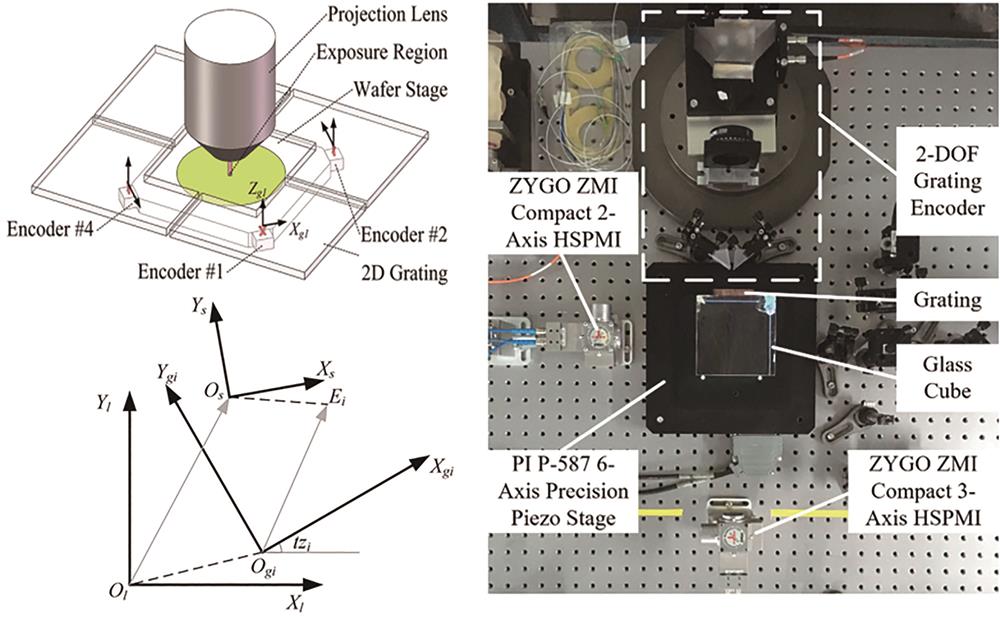
当前,ASML公司率先采用了“四光栅-四读数头”的技术路线,该技术基于四个二自由度的光栅干涉仪和四块二维光栅,每个读数头可以实现一个面内自由度X和一个面外自由度Z的测量,通过四个测量点解算冗余数据可获得晶圆台的六自由度位移,如图16所示1069

图 16. ASML公司采用的“四光栅-四读数头”技术路线

Fig. 16. Technical route of “four gratings-four reading heads” adopted by ASML company

下载图片 查看所有图片

清华大学朱煜教授团队Ye等470针对目前ASML公司采用的海德汉“四光栅-四读数头”技术路线,开展了多读数头与晶圆台坐标系之间的几何关系计算与仿真,并初步搭建测试了该技术路线中的二自由度光栅干涉仪,如图17所示。该系统包含四个读数头和四块不同斜向栅线的二维光栅,每个读数头是外差式二自由度光栅干涉仪,可以实现一个面内自由度X和一个面外自由度Z的测量,通过测量平面正交坐标系的布置可以实现六自由度的位移测量。二自由度读数头体积小,结构紧凑,对光刻机晶圆台的动态性能影响小。但是该系统位移解算复杂,冗余自由度的误差建模困难,并且对光栅栅线方向有极高的要求,存在较多的技术难点。

图 17. 多光栅-多读数头坐标系几何关系运算及二自由度光栅干涉仪测试

Fig. 17. Geometric relation calculation of multi grating multi reading head coordinate system and test of two-degree-of-freedom grating interferometer

下载图片 查看所有图片

5 光栅干涉仪的精度和误差分析

在前文中,光栅干涉仪根据原理可以分为零差式和外差式,无论是哪一种光栅干涉仪,误差分析和量值溯源都是其实现亚纳米精度测量的关键。根据误差源,光栅干涉仪的测量误差可以分为环境误差、安装误差和仪器内在误差。在环境误差方面,由温度、振动导致的空气折射率误差和光学热漂移误差在几十纳米的量级,通常可以通过测量多点环境温度,进行拟合和标定实现折射率补偿71-72。安装误差可以分为阿贝误差、多轴串扰误差和余弦误差,可以通过建立误差几何模型实现补偿73-74。以上两种误差的补偿方法较为成熟,而仪器内在误差的产生原因更为复杂。

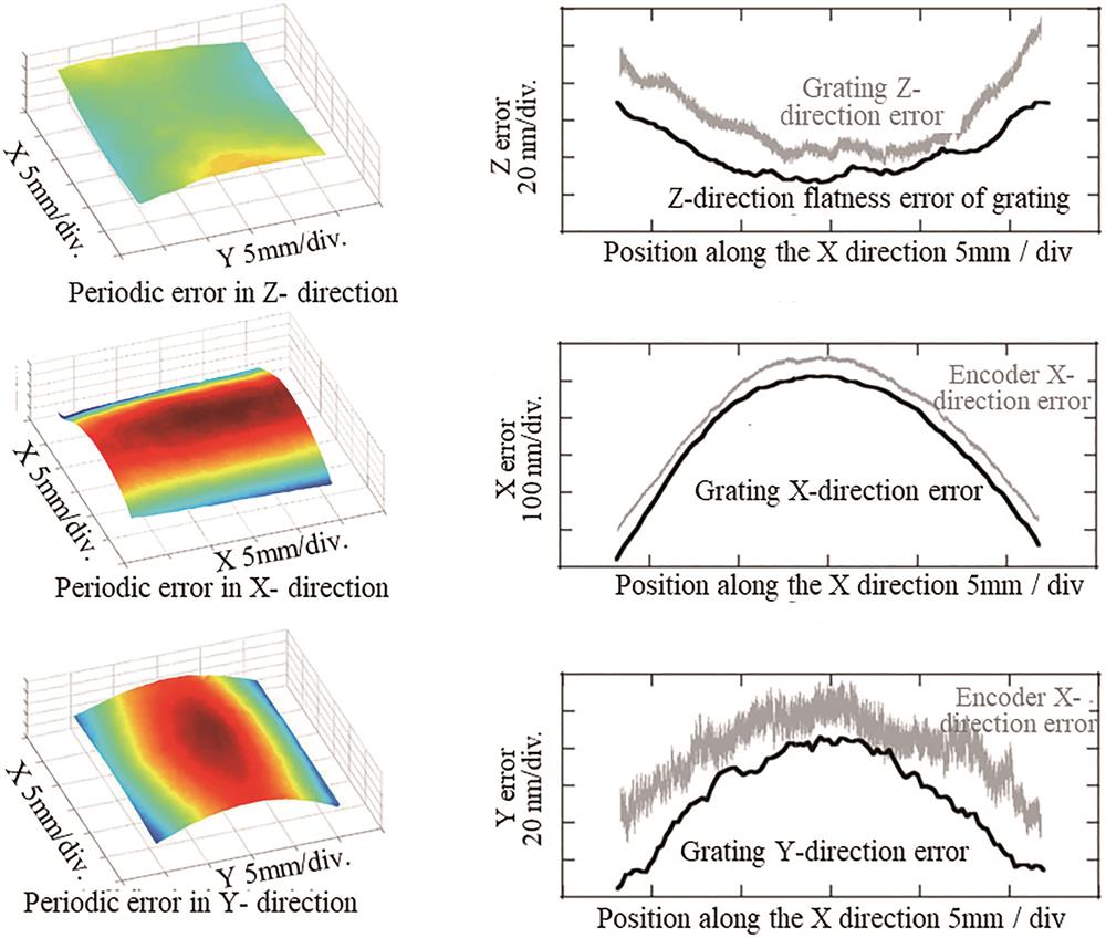
仪器内在误差包括光栅面型误差75、激光源频率/功率稳定性76及周期非线性误差77。光栅面型误差的影响与光栅的制造精度有关,由于激光光斑的直径远大于计量光栅的周期,因此面型误差实际会被数千条栅线所平均,例如对于5 mm的光斑直径和1 μm的光栅周期,即一个光斑覆盖5000条栅线,那么1 μm的光栅型面误差将对测量结果产生级别在0.2 nm左右的误差。为解决大面积光栅面型误差与周期偏差引入的测量误差,日本东北大学Gao等78-80基于斐索干涉仪原理的波前干涉方式获取并分离面型误差和周期偏差,如图18所示。面型误差和周期偏差与实际比对实验所获得的数据具有高一致性,该技术对于光栅干涉仪误差补偿具有重要意义。另一方面,激光源频率/功率稳定性在每1 m测量中会产生纳米级的误差,可以通过对激光源进行锁频和稳频,将该误差降低至每1 m行程下皮米级的水平81

图 18. 基于大面积波前干涉获取的光栅面型误差与周期偏差及其比对结果

Fig. 18. Grating profile error and periodic deviation obtained based on large-area wavefront interference and their comparison results

下载图片 查看所有图片

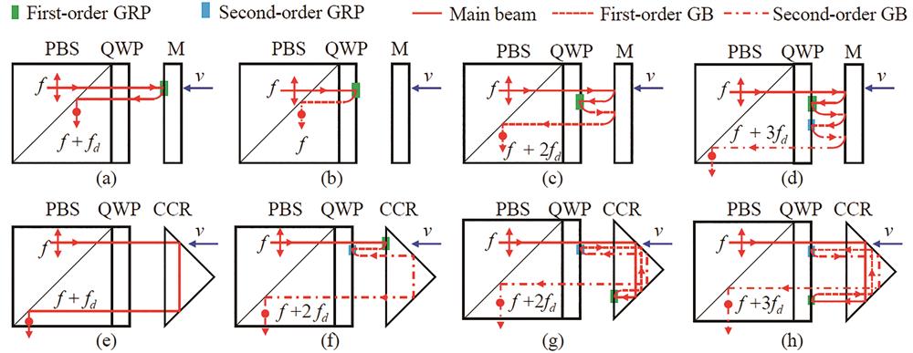
周期非线性误差主要由干涉仪中光学元件虚反射引起82。虚反射是指激光在通过透射或吸收元件时,除了发生向前的透射外,还有一小部分光在元件的各个界面上产生向后的反射,也被称为鬼反射现象。由于光栅在运动过程中,激光会产生多普勒频移,若是激光在光栅和光学元件表面发生多次虚反射,则多普勒频率产生的相位差会加倍,即产生了不同阶次的多普勒频移。Fu等83对基于反射镜的单自由度激光干涉仪的虚反射现象进行了分析,得到了如图19所示的不同多普勒频移阶次的虚反射现象,建立了针对包含干涉仪任意光学界面间多阶虚反射的虚反射光束追迹模型,将虚反射造成的周期非线性误差从39 pm减小至5 pm。

图 19. 不同多普勒频移阶次的虚反射现象

Fig. 19. Virtual reflection phenomenon of different Doppler shift orders

下载图片 查看所有图片

对于外差干涉仪,双频激光偏振混叠和频率混叠也会引起周期非线性误差。通常外差干涉仪是以共光路形式搭建的,即空间中两个偏振方向正交的频率分量以同一束激光的形式射入测量光路,但是由于光源输出光非完全圆偏化、偏振器件的非理想化和安装误差等原因,造成激光的偏振混叠,两个分量会产生频率混叠,引起测量信号存在上下非对称的幅值包络,并导致位移测量产生周期性的非线性波动84-86。为了解决共光路外差干涉仪的偏振混叠和频率混叠现象,非共光路外差干涉仪被提出了,例如台湾工业技术研究院Wu等87早在1999年提出的一款非共光路外差激光干涉仪,清华大学Zhao等88提出的非线性误差在亚纳米级别的外差激光干涉仪,哈尔滨工业大学Hu等89提出的非共光路外差激光干涉仪,非共光路单自由度90、二自由度91-92和三自由度外差光栅干涉仪93等。非共光路外差干涉仪将两个频率分量分开,以两束激光的形式射入光路,最终在探测器上进行45°偏振合光,由于在整个测量光路中,两个频率分量未产生耦合,避免了偏振混叠和频率混叠。

当前,多自由度光栅干涉仪的误差模型仍是复杂且难以溯源的,需要建立完备的误差模型和误差分配机制。首先,对于外差式光栅干涉仪,光栅对激光的偏振态存在调制作用,且光栅对不同方向上的衍射光的偏振调制作用不相同,因此在周期非线性误差分析上,不能简单地以反射镜模型进行分析,多光学元件间的虚反射和频率混叠现象造成的周期非线性误差是外差式光栅干涉仪的关键问题。此外,无论是外差式还是零差式光栅干涉仪,都以光栅栅距为基准,保证大面积光栅加工中计量光栅本身的面型精度和可溯源性是关键研究问题。最后,对于光刻机中高速高动态的测量需求,如何实现高速高动态下的亚纳米精度测量也是一个关键问题。

6 总结

光刻机晶圆台的定位精度对光刻机的制程有重要影响。针对14 nm及以下先进节点光刻机中晶圆台的超精密定位问题,总结了多自由度零差式和外差式光栅干涉测量方案及光栅制造工艺,并对当前“四光栅-四读数头”的读数头布局进行了介绍。最后讨论了光栅干涉仪中精度分析和量值溯源的关键问题,提出了影响光栅干涉仪测量精度的关键问题,为解决光刻机晶圆台六自由度亚纳米定位需求提供参考。

参考文献

[1] National Bureau of Statistics. Statistical bulletin of the people’s Republic of China on national economic and social development in 2021[N]. China Information News, 2022-03-01(1).

    国家统计局. 中华人民共和国2021年国民经济和社会发展统计公报[N]. 中国信息报, 2022-03-01(1). 10.1177/000944550103700211

[2] 池峰, 朱煜, 张志平, 等. 双频激光干涉测量中的环境补偿技术[J]. 中国激光, 2014, 41(4): 0408004.

    Chi F, Zhu Y, Zhang Z P, et al. Environment compensation technologies in dual-frequency laser interferometer measurement system[J]. Chinese Journal of Lasers, 2014, 41(4): 0408004.

[3] Lee J Y, Jiang G G. Displacement measurement using a wavelength-phase-shifting grating interferometer[J]. Optics Express, 2013, 21(21): 25553-25564.

[4] Ye W N, Zhang M, Zhu Y, et al. Real-time displacement calculation and offline geometric calibration of the grating interferometer system for ultra-precision wafer stage measurement[J]. Precision Engineering, 2019, 60: 413-420.

[5] Bryan J B. The Abbé principle revisited: an updated interpretation[J]. Precision Engineering, 1979, 1(3): 129-132.

[6] Zheng F J, Feng Q B, Zhang B, et al. A method for simultaneously measuring 6DOF geometric motion errors of linear and rotary axes using lasers[J]. Sensors, 2019, 19(8): 1764.

[7] Straube G, Fischer Calderón J S, Ortlepp I, et al. A heterodyne interferometer with separated beam paths for high-precision displacement and angular measurements[J]. Nanomanufacturing and Metrology, 2021, 4(3): 200-207.

[8] LeachR. Abbe Error/offset[M]. CIRP encyclopedia of production engineering. Heidelberg: Springer, 2014. 10.1007/978-3-642-35950-7_16793-1

[9] Schmidt R H M. Ultra-precision engineering in lithographic exposure equipment for the semiconductor industry[J]. Philosophical Transactions. Series A, Mathematical, Physical, and Engineering Sciences, 2012, 370(1973): 3950-3972.

[10] Castenmiller T, van de Mast F, de Kort T, et al. Towards ultimate optical lithography with NXT: 1950i dual stage immersion platform[J]. Proceedings of SPIE, 2010, 7640: 623-634.

[11] YaoS X, DongX G, YuanW, et al. The study of overlay mark in self aligned double patterning and solution[C]∥2015 China Semiconductor Technology International Conference, March 15-16, 2015, Shanghai, China. New York: IEEE Press, 2015. 10.1109/cstic.2015.7153355

[12] IEEE. International Roadmap for Devices and Systems (IRDS) [EB/OL]. (2021-10-10)[2022-04-07]. https://irds.ieee.org/editions. 10.1007/978-3-030-18338-7_2

[13] van Herpen R, Oomen T, Kikken E, et al. Exploiting additional actuators and sensors for nano-positioning robust motion control[J]. Mechatronics, 2014, 24(6): 619-631.

[14] Voorhoeve R, de Rozario R, Aangenent W, et al. Identifying position-dependent mechanical systems: a modal approach applied to a flexible wafer stage[J]. IEEE Transactions on Control Systems Technology, 2021, 29(1): 194-206.

[15] Yang R D, Bi Y F, Zhou Q, et al. A background reduction method based on empirical mode decomposition for tunable diode laser absorption spectroscopy system[J]. Optik, 2018, 158: 416-423.

[16] Chen B Y, Zhang E Z, Yan L P, et al. A laser interferometer for measuring straightness and its position based on heterodyne interferometry[J]. The Review of Scientific Instruments, 2009, 80(11): 115113.

[17] 陈本永, 穆瑞珍, 周砚江, 等. 激光合成波长纳米测量干涉仪的非线性误差分析[J]. 中国激光, 2008, 35(2): 240-244.

    Chen B Y, Mu R Z, Zhou Y J, et al. Nonlinear error analysis of laser synthetic-wavelength nanomeasurement interferometer[J]. Chinese Journal of Lasers, 2008, 35(2): 240-244.

[18] Gao W, Kim S W, Bosse H, et al. Measurement technologies for precision positioning[J]. CIRP Annals, 2015, 64(2): 773-796.

[19] Shimizu Y, Chen L C, Kim D W, et al. An insight on optical metrology in manufacturing[J]. Measurement Science and Technology, 2020, 32(4): 042003.

[20] Yu H Y, Chen X L, Liu C J, et al. A survey on the grating based optical position encoder[J]. Optics & Laser Technology, 2021, 143: 107352.

[21] Hu P C, Chang D, Tan J B, et al. Displacement measuring grating interferometer: a review[J]. Frontiers of Information Technology & Electronic Engineering, 2019, 20(5): 631-654.

[22] Gao W, Kimura A. A three-axis displacement sensor with nanometric resolution[J]. CIRP Annals, 2007, 56(1): 529-532.

[23] Kimura A, Gao W, Kim W, et al. A sub-nanometric three-axis surface encoder with short-period planar gratings for stage motion measurement[J]. Precision Engineering, 2012, 36(4): 576-585.

[24] Feng C, Zeng L J, Wang S W. Heterodyne planar grating encoder with high alignment tolerance, especially insensitivity to grating tilts[J]. Proceedings of SPIE, 2013, 8759: 87593L.

[25] Lee J Y, Chen H Y, Hsu C C, et al. Optical heterodyne grating interferometry for displacement measurement with subnanometric resolution[J]. Sensors and Actuators A: Physical, 2007, 137(1): 185-191.

[26] Wu C C, Hsu C C, Lee J Y, et al. Optical heterodyne laser encoder with sub-nanometer resolution[J]. Measurement Science and Technology, 2008, 19(4): 045305.

[27] Wu C C, Hsu C C, Lee J Y, et al. Heterodyne common-path grating interferometer with Littrow configuration[J]. Optics Express, 2013, 21(11): 13322-13332.

[28] de Vine G, Rabeling D S, Slagmolen B J J, et al. Picometer level displacement metrology with digitally enhanced heterodyne interferometry[J]. Optics Express, 2009, 17(2): 828-837.

[29] Yang H X, Yin Z Q, Yang R T, et al. Design for a highly stable laser source based on the error model of high-speed high-resolution heterodyne interferometers[J]. Sensors, 2020, 20(4): 1083.

[30] Yokoyama S, Yokoyama T, Araki T. High-speed subnanometre interferometry using an improved three-mode heterodyne interferometer[J]. Measurement Science and Technology, 2005, 16(9): 1841-1847.

[31] Fu H J, Ji R D, Hu P C, et al. Measurement method for nonlinearity in heterodyne laser interferometers based on double-channel quadrature demodulation[J]. Sensors, 2018, 18(9): 2768.

[32] Yokoyama S, Hori Y, Yokoyama T, et al. A heterodyne interferometer constructed in an integrated optics and its metrological evaluation of a picometre-order periodic error[J]. Precision Engineering, 2018, 54: 206-211.

[33] Teimel A. Technology and applications of grating interferometers in high-precision measurement[J]. Precision Engineering, 1992, 14(3): 147-154.

[34] Magnescale laser scale[EB/OL]. (2022-04-01)[2022-04-07]. https://www.magnescale.com/en/laserscale/. 10.54513/bsj.2022

[35] 王磊杰, 张鸣, 朱煜, 等. 超精密外差利特罗式光栅干涉仪位移测量系统[J]. 光学 精密工程, 2017, 25(12): 2975-2985.

    Wang L J, Zhang M, Zhu Y, et al. A displacement measurement system for ultra-precision heterodyne Littrow grating interferometer[J]. Optics and Precision Engineering, 2017, 25(12): 2975-2985.

[36] 夏豪杰. 高精度二维平面光栅测量系统及关键技术研究[D]. 合肥: 合肥工业大学, 2006: 51-76.

    XiaH J. Research on precise 2-D plane grating measurement system and key technology[D]. Hefei: Hefei University of Technology, 2006: 51-76.

[37] HEIDENHAINKGM282 grid encoder[EB/OL]. (2022-04-01)[2022-04-07]. https://www.heidenhain.com/products/testing-and-inspection-devices/testing-of-machine-tools. 10.1055/s-0029-1204845

[38] Li X H, Wang H H, Ni K, et al. Two-probe optical encoder for absolute positioning of precision stages by using an improved scale grating[J]. Optics Express, 2016, 24(19): 21378-21391.

[39] Shi Y P, Ni K, Li X H, et al. Highly accurate, absolute optical encoder using a hybrid-positioning method[J]. Optics Letters, 2019, 44(21): 5258-5261.

[40] Shi Y P, Zhou Q, Li X H, et al. Design and testing of a linear encoder capable of measuring absolute distance[J]. Sensors and Actuators A: Physical, 2020, 308: 111935.

[41] Lin C B, Yan S H, Du Z G, et al. High-efficiency gold-coated cross-grating for heterodyne grating interferometer with improved signal contrast and optical subdivision[J]. Optics Communications, 2015, 339: 86-93.

[42] Zhu Z B, Wu G H. Dual-comb ranging[J]. Engineering, 2018, 4(6): 772-778.

[43] Lin J, Guan J, Wen F, et al. High-resolution and wide range displacement measurement based on planar grating[J]. Optics Communications, 2017, 404: 132-138.

[44] 林杰, 关健, 金鹏, 等. 一种使用双频激光的三维光栅位移测量系统: CN103644848A[P]. 2014-03-19.

    LinJ, GuanJ, JinP, et al. Three-dimensional grating displacement measuring system with dual-frequency laser: CN103644848A[P]. 2014-03-19.

[45] Hsieh H L, Pan S W. Three-degree-of-freedom displacement measurement using grating-based heterodyne interferometry[J]. Applied Optics, 2013, 52(27): 6840-6848.

[46] Gao W, Saito Y, Muto H, et al. A three-axis autocollimator for detection of angular error motions of a precision stage[J]. CIRP Annals, 2011, 60(1): 515-518.

[47] Li X H, Gao W, Muto H, et al. A six-degree-of-freedom surface encoder for precision positioning of a planar motion stage[J]. Precision Engineering, 2013, 37(3): 771-781.

[48] Li X H, Shimizu Y, Ito T, et al. Measurement of six-degree-of-freedom planar motions by using a multiprobe surface encoder[J]. Optical Engineering, 2014, 53(12): 122405.

[49] Lee C, Kim G H, Lee S K. Design and construction of a single unit multi-function optical encoder for a six-degree-of-freedom motion error measurement in an ultraprecision linear stage[J]. Measurement Science and Technology, 2011, 22(10): 105901.

[50] Hsieh H L, Pan S W. Development of a grating-based interferometer for six-degree-of-freedom displacement and angle measurements[J]. Optics Express, 2015, 23(3): 2451-2465.

[51] Yu K N, Zhu J H, Yuan W H, et al. Two-channel six degrees of freedom grating-encoder for precision-positioning of sub-components in synthetic-aperture optics[J]. Optics Express, 2021, 29(14): 21113.

[52] Lin C B, Yan S H, Wei C H, et al. Optimized design and error analysis of optical system for heterodyne grating interferometry[J]. Proceedings of SPIE, 2013, 9046: 90460C.

[53] Shimizu Y. Laser interference lithography for fabrication of planar scale gratings for optical metrology[J]. Nanomanufacturing and Metrology, 2021, 4(1): 3-27.

[54] WeiG. Precision nanometrology[M]. London: Springer, 2010. 10.1007/978-1-84996-254-4

[55] Jain K, Zemel M, Klosner M. Large-area high-resolution lithography and photoablation systems for microelectronics and optoelectronics fabrication[J]. Proceedings of the IEEE, 2002, 90(10): 1681-1688.

[56] Lu C, Lipson R H. Interference lithography: a powerful tool for fabricating periodic structures[J]. Laser & Photonics Reviews, 2010, 4(4): 568-580.

[57] Ma D H, Zeng L J. Fabrication of low-stray-light gratings by broad-beam scanning exposure in the direction perpendicular to the grating grooves[J]. Optics Letters, 2015, 40(7): 1346-1349.

[58] Ma D, Zhao Y, Zeng L. Achieving unlimited recording length in interference lithography via broad-beam scanning exposure with self-referencing alignment[J]. Scientific Reports, 2017, 7: 926.

[59] Shi L, Zeng L J, Li L F. Fabrication of optical mosaic gratings with phase and attitude adjustments employing latent fringes and a red-wavelength dual-beam interferometer[J]. Optics Express, 2009, 17(24): 21530-21543.

[60] Shi L, Zeng L J. Fabrication of optical mosaic gratings: a self-referencing alignment method[J]. Optics Express, 2011, 19(10): 8985-8993.

[61] Zhou H Y, Zeng L J. Optical mosaic method for orthogonally crossed gratings by utilizing information about both main periodic directions simultaneously[J]. Optics Communications, 2017, 385: 181-187.

[62] Li X H, Ni K, Zhou Q, et al. Fabrication of a concave grating with a large line spacing via a novel dual-beam interference lithography method[J]. Optics Express, 2016, 24(10): 10759-10766.

[63] Li X H, Zhou Q, Zhu X W, et al. Holographic fabrication of an arrayed one-axis scale grating for a two-probe optical linear encoder[J]. Optics Express, 2017, 25(14): 16028-16039.

[64] Li X H, Gao W, Shimizu Y, et al. A two-axis Lloyd's mirror interferometer for fabrication of two-dimensional diffraction gratings[J]. CIRP Annals, 2014, 63(1): 461-464.

[65] Li X H, Lu H O, Zhou Q, et al. An orthogonal type two-axis lloyd's mirror for holographic fabrication of two-dimensional planar scale gratings with large area[J]. Applied Sciences, 2018, 8(11): 2283.

[66] Li X H, Shimizu Y, Ito S, et al. Fabrication of scale gratings for surface encoders by using laser interference lithography with 405 nm laser diodes[J]. International Journal of Precision Engineering and Manufacturing, 2013, 14(11): 1979-1988.

[67] Xue G P, Lu H O, Li X H, et al. Patterning nanoscale crossed grating with high uniformity by using two-axis Lloyd’s mirrors based interference lithography[J]. Optics Express, 2020, 28(2): 2179-2191.

[68] Xue G, Zhai Q, Lu H, et al. Polarized holographic lithography system for high-uniformity microscale patterning with periodic tunability[J]. Microsystems & Nanoengineering, 2021, 7: 31.

[69] de Jong F, van der Pasch B, Castenmiller T, et al. Enabling the lithography roadmap: an immersion tool based on a novel stage positioning system[J]. Proceedings of SPIE, 2009, 7274: 608-617.

[70] Ye W N, Zhang M, Zhu Y, et al. Ultraprecision real-time displacements calculation algorithm for the grating interferometer system[J]. Sensors, 2019, 19(10): 2409.

[71] Kang H J, Chun B J, Jang Y S, et al. Real-time compensation of the refractive index of air in distance measurement[J]. Optics Express, 2015, 23(20): 26377-26385.

[72] Weichert C, Köchert P, Köning R, et al. A heterodyne interferometer with periodic nonlinearities smaller than ±10 pm[J]. Measurement Science and Technology, 2012, 23(9): 094005.

[73] Chen G H, Zhang L, Wang X J, et al. Modeling method of CNC tooling volumetric error under consideration of Abbé error[J]. The International Journal of Advanced Manufacturing Technology, 2022, 119(11/12): 7875-7887.

[74] Liu H W, Xiang H, Chen J H, et al. Measurement and compensation of machine tool geometry error based on Abbé principle[J]. The International Journal of Advanced Manufacturing Technology, 2018, 98(9/10/11/12): 2769-2774.

[75] 吴新朴, 韦怀坤, 刘正坤, 等. 用于检测光栅线密度的长程面形仪系统[J]. 光学学报, 2021, 41(6): 0612002.

    Wu X P, Wei H K, Liu Z K, et al. Long trace profiler for measuring groove density of diffraction gratings[J]. Acta Optica Sinica, 2021, 41(6): 0612002.

[76] 高静, 焦东东, 刘杰, 等. 基于短光纤循环自外差法的激光线宽测量[J]. 光学学报, 2021, 41(7): 0712002.

    Gao J, Jiao D D, Liu J, et al. Laser linewidth measurement based on recirculating self-heterodyne method with short fiber[J]. Acta Optica Sinica, 2021, 41(7): 0712002.

[77] 张博, 严利平, 刁晓飞. 波片阵列对准误差对激光干涉非线性误差的影响[J]. 中国激光, 2022, 49(9): 0904003.

    Zhang B, Yan L P, Diao X F. Effect of alignment error of wave plate array on nonlinear error of laser interference[J]. Chinese Journal of Lasers, 2022, 49(9): 0904003.

[78] Gao W, Kimura A. A fast evaluation method for pitch deviation and out-of-flatness of a planar scale grating[J]. CIRP Annals, 2010, 59(1): 505-508.

[79] Xiong X, Shimizu Y, Chen X G, et al. Uncertainty evaluation for measurements of pitch deviation and out-of-flatness of planar scale gratings by a Fizeau interferometer in Littrow configuration[J]. Applied Sciences, 2018, 8(12): 2539.

[80] Quan L, Shimizu Y, Xiong X, et al. A new method for evaluation of the pitch deviation of a linear scale grating by an optical angle sensor[J]. Precision Engineering, 2021, 67: 1-13.

[81] Yang H X, Yang R T, Hu P C, et al. Ultrastable offset-locked frequency-stabilized heterodyne laser source with water cooling[J]. Applied Optics, 2017, 56(33): 9179-9185.

[82] Fu H J, Wang Y, Hu P C, et al. Nonlinear errors resulting from ghost reflection and its coupling with optical mixing in heterodyne laser interferometers[J]. Sensors, 2018, 18(3): 758.

[83] Fu H J, Wang Y, Hu P C, et al. Real-time compensation of nonlinearity in heterodyne interferometers based on quadrature demodulation and extremum operation[J]. Optical Engineering, 2020, 59(4): 044101.

[84] 郝义伟, 孔新新, 才啟胜, 等. 环形器噪声对激光干涉测量系统影响分析[J]. 光学学报, 2021, 41(9): 0912003.

    Hao Y W, Kong X X, Cai Q S, et al. Analysis of effect of circulator noise on laser interferometry system[J]. Acta Optica Sinica, 2021, 41(9): 0912003.

[85] Cosijns S J A G, Haitjema H, Schellekens P H J. Modeling and verifying non-linearities in heterodyne displacement interferometry[J]. Precision Engineering, 2002, 26(4): 448-455.

[86] Yang Y, Deng Y, Tan Y D, et al. Nonlinear error analysis and experimental measurement of Birefringence-Zeeman dual-frequency laser interferometer[J]. Optics Communications, 2019, 436: 264-268.

[87] Wu C M, Lawall J, Deslattes R D. Heterodyne interferometer with subatomic periodic nonlinearity[J]. Applied Optics, 1999, 38(19): 4089-4094.

[88] Zhao S J, Wei H Y, Zhu M H, et al. Green laser interferometric metrology system with sub-nanometer periodic nonlinearity[J]. Applied Optics, 2016, 55(11): 3006-3011.

[89] Hu P C, Chen P, Diao X F, et al. Highly stable heterodyne interferometer without periodic nonlinearity[J]. Tm-Technisches Messen, 2014, 81(5): 246-254.

[90] Xing X, Chang D, Hu P C, et al. Spatially separated heterodyne grating interferometer for eliminating periodic nonlinear errors[J]. Optics Express, 2017, 25(25): 31384-31393.

[91] 邢旭, 常笛, 胡鹏程, 等. 空间分离式外差二自由度平面光栅干涉仪[J]. 光学 精密工程, 2019, 27(8): 1727-1736.

    Xing X, Chang D, Hu P C, et al. Spatially separated heterodyne grating interferometer for in-plane displacement measurement[J]. Optics and Precision Engineering, 2019, 27(8): 1727-1736.

[92] Chang D, Xing X, Hu P C, et al. Double-diffracted spatially separated heterodyne grating interferometer and analysis on its alignment tolerance[J]. Applied Sciences, 2019, 9(2): 263.

[93] 胡鹏程, 谭久彬, 陈朋. 抗光学混叠的双频激光光栅干涉三维测量方法及系统: CN103604376B[P]. 2017-02-01.

    HuP C, TanJ B, ChenP. Double frequency laser grating interference three-dimensional measurement method and system with optical aliasing resistance: CN103604376B[P]. 2017-02-01.

朱俊豪, 汪盛通, 李星辉. 面向光刻机晶圆台的超精密光栅定位技术[J]. 激光与光电子学进展, 2022, 59(9): 0922019. Junhao Zhu, Shengtong Wang, Xinghui Li. Ultraprecision Grating Positioning Technology for Wafer Stage of Lithography Machine[J]. Laser & Optoelectronics Progress, 2022, 59(9): 0922019.
引用该论文: TXT   |   EndNote

相关论文

加载中...

关于本站 Cookie 的使用提示

中国光学期刊网使用基于 cookie 的技术来更好地为您提供各项服务,点击此处了解我们的隐私策略。 如您需继续使用本网站,请您授权我们使用本地 cookie 来保存部分信息。
全站搜索
您最值得信赖的光电行业旗舰网络服务平台!